Rapid tunable microfiber ring resonator

A ring resonant cavity and micro-fiber technology, applied in the field of micro-optical components, can solve the problems of slow response and large temperature device, and achieve the effect of good stability and fast adjustability

Inactive Publication Date: 2012-08-01
NANJING UNIV
View PDF1 Cites 10 Cited by
  • Summary
  • Abstract
  • Description
  • Claims
  • Application Information

AI Technical Summary

Problems solved by technology

Many practical applications require external adjustment of the resonant wavelength or output power of the resonant cavity, the introduction of external modulation signals, etc. The traditional tuning technology of the resonant cavity is generally based on the adj

Method used


Image

  • Rapid tunable microfiber ring resonator
  • Rapid tunable microfiber ring resonator
  • Rapid tunable microfiber ring resonator

Examples


Embodiment Construction

[0016] Below in conjunction with accompanying drawing and embodiment the present invention will be further described:

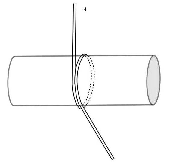
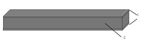
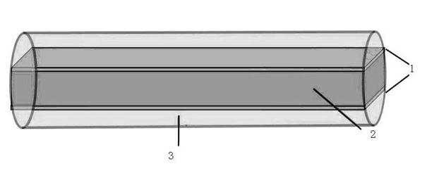
[0017] like figure 1 , shown in 2, an example of the present invention is to paste two metal electrodes 1 on the upper and lower sides of the piezoelectric ceramic (PZT) dielectric rod 2, and draw out a lead respectively, evenly smear Telfon3 on the piezoelectric ceramic dielectric rod to form Cylindrical medium rod. Then the micro-fiber 4 is wound on the dielectric rod to form a resonant cavity. Finally, use Telfon3 package and place in air to cure.

[0018] In this example, the diameter of the micro-optical fiber is 2um, and the length of the waist area (two turns of the winding area) is about 25mm. The size of the piezoelectric ceramic rod is 1 mm × 2 mm × 6 mm. The cylindrical dielectric rod has a diameter of about 2.5 mm, and the largest diameter of the dielectric rod is generally not more than 2 cm. The diameter of the ring resonant cavity is dete...


PUM

PropertyMeasurementUnit
Diameteraaaaaaaaaa
Diameteraaaaaaaaaa
Diameteraaaaaaaaaa

Abstract

The invention discloses a rapid tunable microfiber ring resonator, which is characterized in that a microfiber is wound on a support bar made of material with piezoelectric or magnetostrictive property so as to form an optical resonator, contact parts of ring microfiber are coupled, one end of a taper fiber is an optical signal input end, the other end of the taper fiber is an optical signal output end, and the resonance properties (such as resonant wavelength, output power and phase information and the like) of the resonator are adjusted rapidly through changing the size of a voltage or a magnetic field.

Description

technical field [0001] The invention relates to a micro-optical element, in particular to a preparation method of an optical phase modulator based on a micro-fiber ring resonant cavity supported by a piezoelectric ceramic dielectric rod and a wavelength tuning technology. Background technique [0002] Fiber resonators have a wide range of applications in sensing and communication. With the development of micro-fiber manufacturing technology, small-sized micro-fiber resonators have been successfully demonstrated, and the multi-ring resonator prepared by surround technology has a high degree of integration due to its strong coupling, large design and manufacturing freedom , easy encapsulation and other advantages have great application prospects, and have received a high degree of attention. Many practical applications require external adjustment of the resonant wavelength or output power of the resonant cavity, the introduction of external modulation signals, etc. The tradi...

Claims


Application Information

Patent Timeline
IPC IPC(8): G02F1/01
Inventor 徐飞陈烨李程陆延青胡伟
Owner NANJING UNIV
Why Eureka
Try Eureka