Antenna for wireless communication and wireless communication device

A wireless communication and antenna technology, applied in the directions of antennas, resonant antennas, antenna components, etc., can solve problems such as difficulties and achieve the effect of preventing leakage

Active Publication Date: 2015-09-23
TDK CORPARATION
View PDF7 Cites 0 Cited by
  • Summary
  • Abstract
  • Description
  • Claims
  • Application Information

AI Technical Summary

Problems solved by technology

In the conventional resonator structure described in Patent Document 1, it is difficult to prevent leakage of signals (electromagnetic waves) propagating far away while realizing short-distance high-speed wireless communication

Method used


Image

  • Antenna for wireless communication and wireless communication device
  • Antenna for wireless communication and wireless communication device
  • Antenna for wireless communication and wireless communication device

Examples


no. 1 Embodiment approach

[0079] 【Basic structure of an antenna for wireless communication】

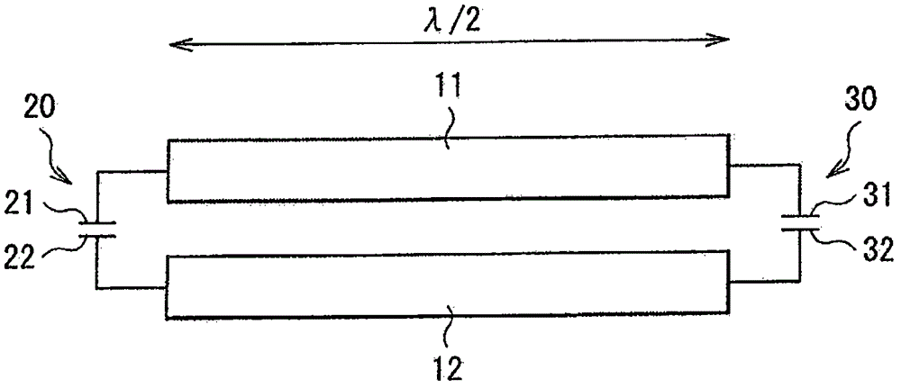
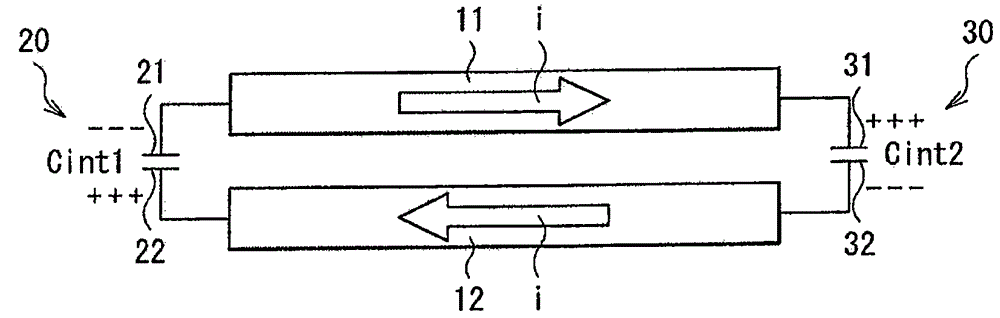
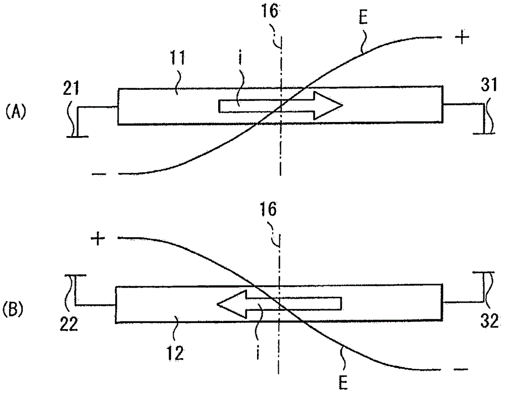
[0080] figure 1 The basic configuration of the wireless communication antenna according to the first embodiment of the present invention is shown. This wireless communication antenna includes a first half-wavelength resonator 11 (first resonator), a second half-wavelength resonator 12 (second resonator), a first capacitor 20 , and a second capacitor 30 .

[0081] The first half-wavelength resonator 11 and the second half-wavelength resonator 12 respectively have both ends as open ends, and are arranged in parallel with each other (for example, arranged in parallel in the same plane or arranged in parallel in the vertical direction) so that the open ends of each other are opposite to each other. place. The first capacitor 20 and the second capacitor 30 are connected between open ends of the first half-wavelength resonator 11 and the second half-wavelength resonator 12 facing each other.

[0082] More specifi...

no. 2 Embodiment approach

[0117] Next, a wireless communication antenna according to a second embodiment of the present invention will be described. In addition, the same reference numerals are given to the substantially same components as those of the wireless communication antenna of the first embodiment described above, and description thereof will be appropriately omitted.

[0118] 【Basic structure of an antenna for wireless communication】

[0119] Figure 20 The basic configuration of the wireless communication antenna according to the second embodiment of the present invention is shown. This wireless communication antenna includes a first quarter-wavelength resonator 51 (first resonator), a second quarter-wavelength resonator 52 (second resonator), and a first capacitor 20 .

[0120] The first quarter-wavelength resonator 51 and the second quarter-wavelength resonator 52 respectively have one end as an open end and the other end as a short-circuit end, and the first quarter-wavelength resonator...


PUM


Abstract

An antenna includes: a first resonator and a second resonator each having an open end, in which the first resonator and the second resonator are disposed side by side to allow the open ends thereof to be opposed to each other; and a first capacitor connected between the open ends which are opposed to each other.

Description

technical field [0001] The present invention relates to an antenna for wireless communication and a wireless communication device for transmitting signals (electromagnetic waves) in a short distance. Background technique [0002] Conventionally, there is known a signal transmission device that performs signal transmission using a plurality of substrates each forming a resonator. For example, Patent Document 1 discloses a technique in which resonators are formed on different substrates, and these resonators are electromagnetically coupled to each other to form a two-stage filter for signal transmission. [0003] Patent Document 1: Japanese Patent Laid-Open No. 2008-67012 [0004] In general, in an antenna for wireless communication using a resonator, there are components of electromagnetic waves radiated from the antenna that propagate far away and components that propagate only in the vicinity of the antenna. At this time, the intensity of the component transmitted far awa...

Claims


Application Information

Patent Timeline
Patent Type & Authority Patents(China)
IPC IPC(8): H01Q23/00H04B1/40H01Q9/04
CPCH01Q1/526H01Q23/00H01Q9/04
Inventor 福永达也
Owner TDK CORPARATION
Why Eureka
Try Eureka