Small-range electromagnetic eccentric magnetic gear pair with novel radial magnetic field

A magnetic gear and radial magnetic field technology, applied in the direction of magnetic circuit shape/style/structure, motor, electromechanical device, etc., can solve the problems of unadjustable, permanent magnet magnetic flux reduction, large mechanical torque, etc., to eliminate gear hysteresis Effects of trouble, increased torque density, and increased life limit

Inactive Publication Date: 2014-06-11
余虹锦
View PDF4 Cites 0 Cited by
  • Summary
  • Abstract
  • Description
  • Claims
  • Application Information

AI Technical Summary

Problems solved by technology

[0004] The above-mentioned magnetic gears designed based on the magnetic field modulation technology have two fatal deficiencies in terms of theoretical principles and structural solutions: First, theoretically, the number of poles (teeth) of the magnetic permeable grid core that plays the role of magnetic field modulation must meet the constraint conditions , resulting in less than half of the permanent magnets of the magnetic gear being in the working state of mutual magnetic field coupling at any time during the transmission of the magnetic gear, and more than half of the permanent magnet poles being in the idle non-coupling state, that is, the coupling degree theory of rare earth permanent magnet poles Second, from a structural point of view, adding a magnetic grid core will inevitably make the magnetic gear pair have two air gaps, which will inevitably consume a large amount of magnetomotive force of the rare earth permanent magnet. If the magnetic pole is not thickened The thickness will inevitably lead to the reduction of the magnetic flux of the permanent magnet in the coupled working state, thereby affecting the magnitude of the transmitted torque; third, the existence of the magnetic grid core makes the air gap reluctance and magnetic potential alternately pulsating, resulting in periodic torque fluctuations , not only affects the transmission accuracy, but also the mechanical torque on the magnetic grid core is large, and its structural strength is also the main factor affecting its life
[0005] Recently, one of the inventors of this case has also proposed a new type of eccentric magnetic gear pair (201110277432.3, 201120350893.4 and 201110355864.1, 201120444409.4) with a new type of transverse and radial magnetic field magnetic field coupling type eccentricity. Two permanent magnetic fields with different numbers of poles interact and couple each other to achieve the purpose of torque transmission and variable speed transmission. However, the concept of double permanent magnetic coupling variable speed with less pole difference cannot be realized because the permanent magnetic field of rare earth materials cannot be adjusted. Clutch control, let alone automatically adjust the torque according to the load, can only achieve the purpose of simple variable speed transmission. So far, no one at home and abroad has proposed to use the principle of electromagnetic field to improve the working principle of the eccentric magnetic gear pair with less extreme deviation and specific application structures, but such technical research and structural inventions have important practical significance for applications that require both clutch functions and variable speed and torque.

Method used


Image

  • Small-range electromagnetic eccentric magnetic gear pair with novel radial magnetic field
  • Small-range electromagnetic eccentric magnetic gear pair with novel radial magnetic field

Examples


Embodiment Construction

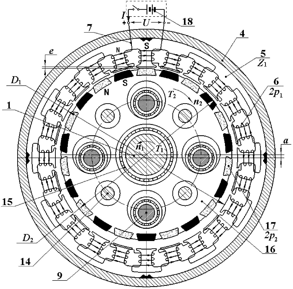
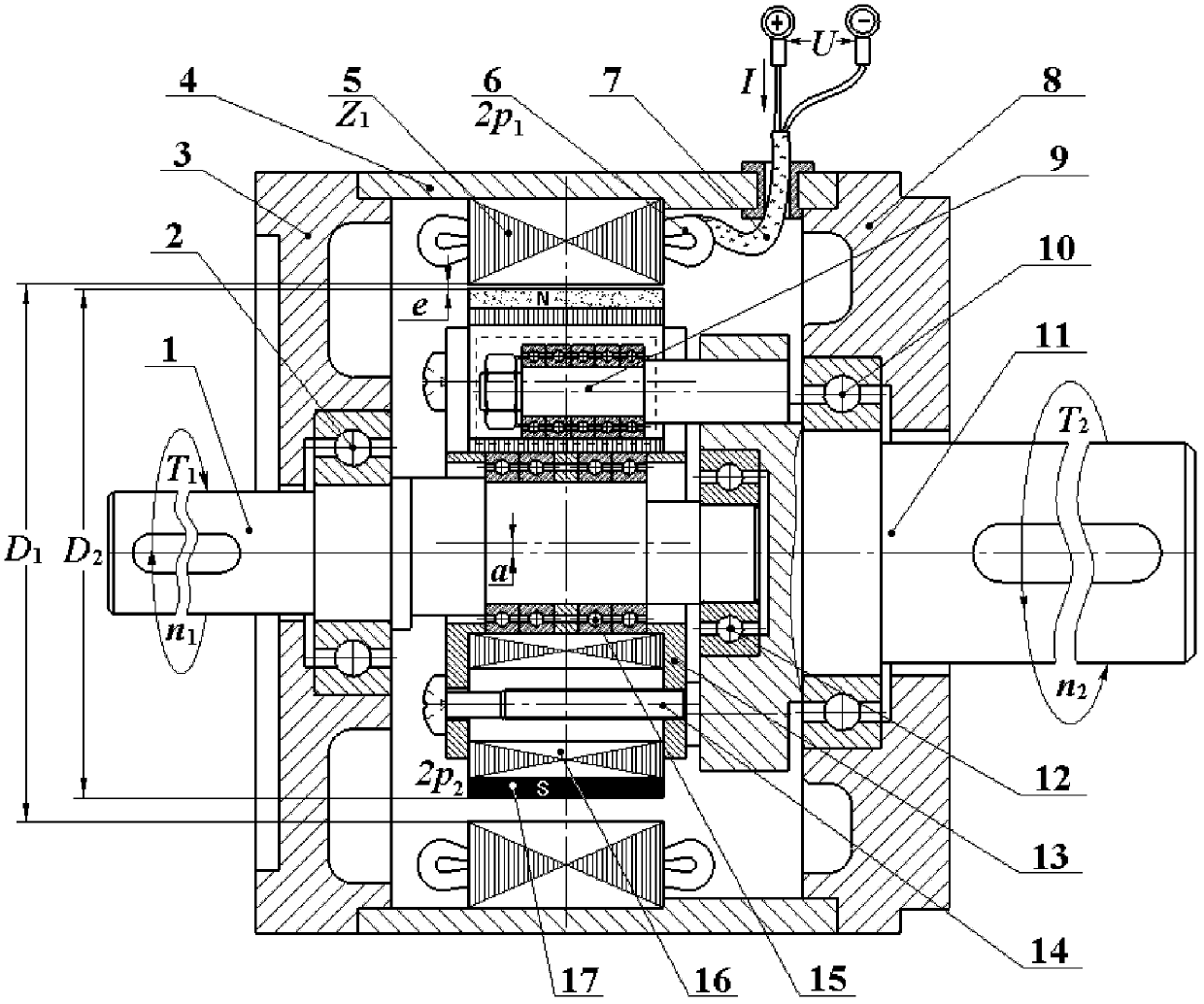
[0024] Below in conjunction with accompanying drawing and specific embodiment, the present invention will be further described: figure 1 It is a topological diagram of the working principle of the radial structure of the eccentric magnetic gear pair with few extreme differences in the radial magnetic field. figure 2 It is a full cross-sectional view of the axial structure of the electromagnetic eccentric magnetic gear pair with few extreme differences in the radial magnetic field.

[0025] 1. The working principle of the electromagnetic eccentric magnetic gear pair with less polar difference in the radial magnetic field is as follows: when working, the current I provided by the external power supply 18 with a voltage of U passes through the stator winding 6 to establish a pole number of 2p 1 The stator electromagnetic field, the eccentric input shaft 1 drives the planetary rotor core 16 to revolve around the axis of rotation, and the rotor permanent magnet 17 on the eccentric...


PUM


Abstract

The invention discloses a small-range electromagnetic eccentric magnetic gear pair with a radial magnetic field, and can be widely applied to the field of transmission of industries such as wind power generation, electric vehicles and ship driving. The magnetic gear pair is characterized by consisting of a stator and a planetary rotor, wherein the stator consists of a stator enclosure 4, a stator core 5 with Z1 coil inserting slots and 2p1 stator windings 6 arranged in the slots; the planetary stator consists of a planetary rotor core 16 and 2p2 rotor permanent magnets 17 distributed on the outer circle of the planetary rotor core 16; pole pair numbers p1 and p2 have a small number difference, and are co-prime; the small-range stator is connected with the planetary rotor through an eccentric input shaft 1 on which a bearing IV15 is sleeved to form an eccentric structure; planetary rotor is driven by the eccentric input shaft 1 to revolve about a rotating shaft; a permanent magnetic field of the planetary rotor is coupled with an electromagnetic field of the stator through a radially eccentric air gap; the rotor permanent magnets 17 drive the planetary rotor under the action of the electromagnetic field of the stator to backwards rotate about own axis; and low-speed rotation is output through an output mechanism 9 and an output shaft 11.

Description

technical field [0001] The present invention is an electromagnetic eccentric magnetic gear pair with less extreme difference in the radial magnetic field. It utilizes electromagnetic magnetic gear transmission technology to realize the mutual conversion of high-speed, small-torque mechanical energy and low-speed, high-torque mechanical energy. It directly replaces the conventional mechanical gear transmission clutch transmission system, and is widely used in wind power generation, hydropower generation, electric vehicles, ship drive and other industrial transmission fields that require direct drive. Background technique [0002] In many transmission fields of industrial applications, it is often necessary to realize the mutual conversion of low-speed, high-torque mechanical energy and high-speed, low-torque mechanical energy. High-speed mechanical kinetic energy for power generation, electric vehicles and submarine drives need to convert the high-speed mechanical power of th...

Claims


Application Information

Patent Timeline
Patent Type & Authority Patents(China)
IPC IPC(8): H02K51/00H02K1/16
CPCY02T10/641Y02T10/64
Inventor 卢敏胡捷余虹锦
Owner 余虹锦
Why Eureka
Try Eureka