
Circumfluent cooling dehumidifying barn

A cooling and dehumidification technology for granaries, applied in the field of granaries, can solve problems such as dead angles and incomplete ventilation, and achieve the effects of saving labor, solving dead angles of ventilation, and uniform drying degree

Inactive Publication Date: 2012-08-08
INST OF AGRO FOOD SCI & TECH SHANDONG ACAD OF AGRI SCI
View PDF6 Cites 6 Cited by
  • Summary
  • Abstract
  • Description
  • Claims
  • Application Information

AI Technical Summary

Problems solved by technology

[0003] The object of the present invention is to provide a circulation cooling and dehumidification granary, which mainly solves the technical problems of incomplete ventilation and dead angles in the prior art

Method used


Image

  • Circumfluent cooling dehumidifying barn
  • Circumfluent cooling dehumidifying barn

Examples


Embodiment Construction

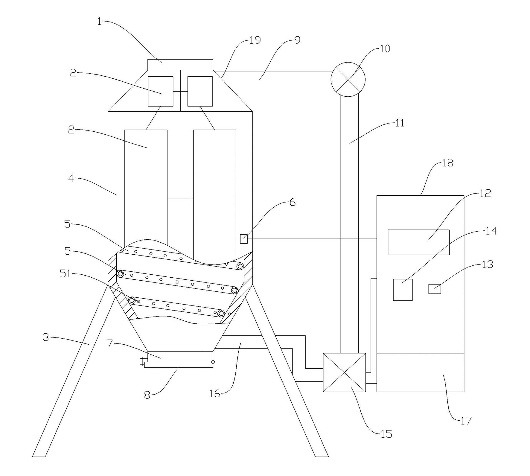
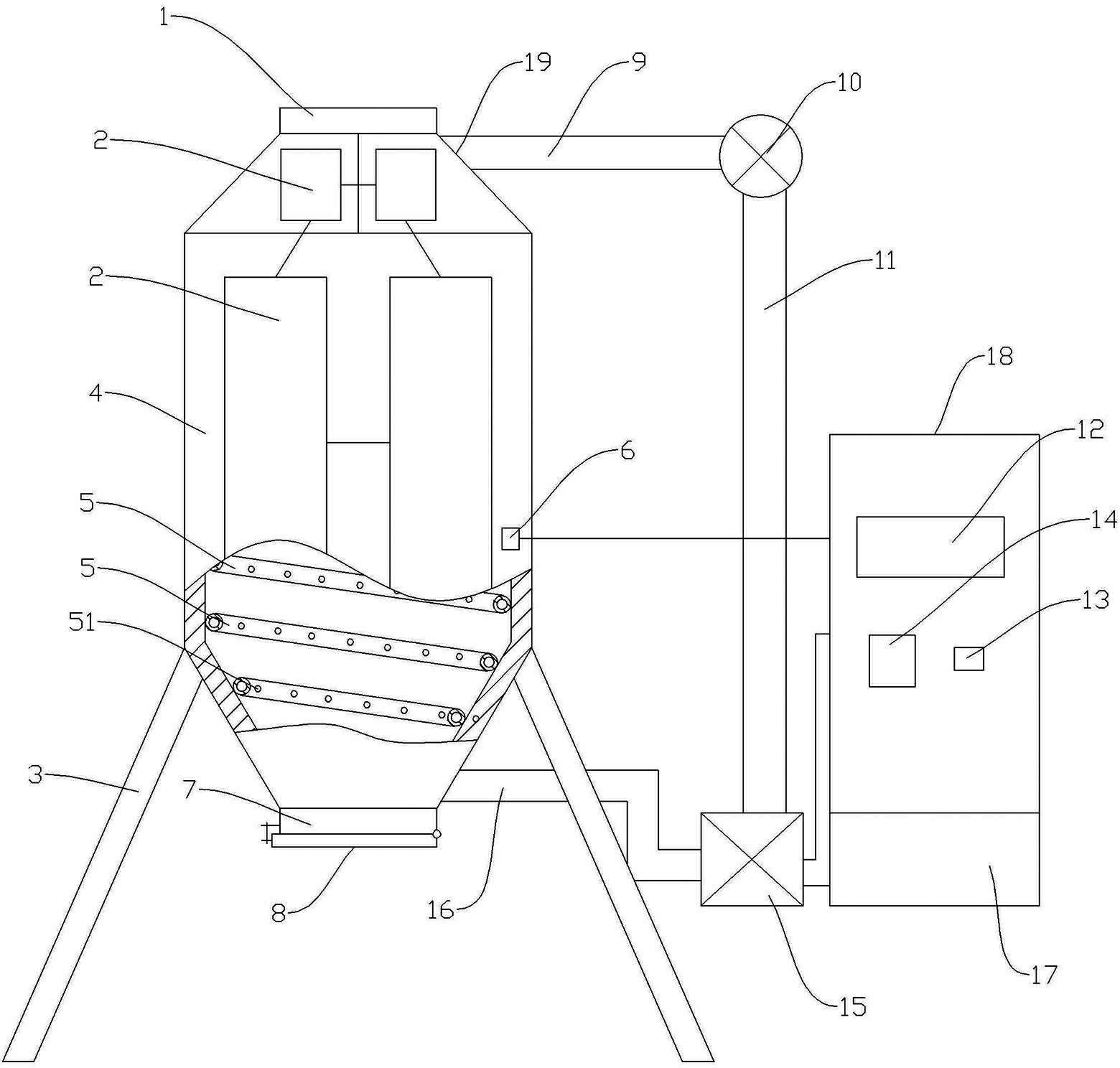
[0014] Such as figure 1 shown. A circulating cooling and dehumidifying granary mainly includes a granary main body, a granary support 3 , a solar panel 2 , and a control cabinet 18 .

[0015] The main body of the granary includes a granary top cover 1 and a silo body 4; the bottom of the silo body is provided with a grain outlet 7 of the silo body, and the grain outlet 7 of the silo body is provided with a grain outlet sealing plate 8; Temperature and humidity probe 6.

[0016] The control cabinet 18 is located outside the warehouse body 4 . The solar panel 2 is fixed on the outer surface of the bin body 4 .

[0017] The inner wall of the bin body 4 is fixed with a spiral ventilation duct 5 spiraling upward around the center line of the bin body. Several through holes 51 are provided on the pipe wall of the spiral ventilation pipe 5 .

[0018] The bottom of the spiral air duct 5 communicates with one end of the air blast duct 16 located outside the warehouse bo...


PUM


Abstract

The invention relates to a circumfluent cooling dehumidifying barn mainly solving the technical problems in the prior art that ventilation is not thorough and dead corner exists in the ventilation. The circumfluent cooling dehumidifying barn comprises a barn main body and a barn frame; the barn main body comprises a barn top cover and a cabin body; a cabin body grain outlet is arranged on the bottom part of the cabin body, and a grain outlet sealing plate is arranged on the cabin body grain outlet; a temperature-humidity probe is arranged on the inner wall of the cabin body; and the circumfluent cooling dehumidifying barn is characterized in that a spiral ventilation pipeline which is screwed upwards along the central line of the cabin body is arranged on the inner wall of the cabin body; a plurality of through holes are arranged on the wall of the spiral ventilation pipeline; the bottom end of the spiral ventilation pipeline is communicated with one end of a blowing pipeline which is arranged outside the cabin body on the bottom part of the cabin body; the other end of the blowing pipeline is communicated with an air outlet side of a blowing fan; an air outlet is arranged on the top part of the cabin body, and the air outlet is communicated with one end of an air outlet pipe which is arranged outside the cabin body; and the other end of the air outlet pipe is communicated with an air return pipe through a pipeline air outlet changeover switch, and the air return pipe is communicated to the air inlet side of the blowing fan.

Description

technical field [0001] The invention relates to the technical field of granaries, in particular to a granary with the function of cooling and dehumidifying. Background technique [0002] At present, the ventilation and cooling of granaries mostly use artificial fans. By artificially observing the temperature and humidity sensors in the granaries, the fans are turned on to cool down and dehumidify. In places with high technology, there are also electronic control methods for automatic detection and automatic cooling. However, the diversion method inside the granary adopts the straight-through method. change; and the above methods are all carried out by using an external AC power supply method, and there are deficiencies in terms of safety and energy saving. Contents of the invention [0003] The object of the present invention is to provide a circulating cooling and dehumidifying granary, which mainly solves the technical problems of incomplete ventilation and dead angles ...

Claims


Application Information

Patent Timeline
Patent Type & Authority Applications(China)
IPC IPC(8): A01F25/14A01F25/22
CPCY02A40/58
Inventor 汝医陈军赵晓燕陈锋亮李明华王宪昌段友臣邓鹏
Owner INST OF AGRO FOOD SCI & TECH SHANDONG ACAD OF AGRI SCI
Learn More