Vehicular rear wheel steering device

A rear wheel steering device and vehicle technology, which is applied to steering mechanisms, steering rods, vehicle components, etc., can solve problems such as operating limitations of spline structures, increasing wear at the ends of connecting rods and sliding parts of the housing, etc.

Inactive Publication Date: 2012-08-08
AISIN SEIKI KK
View PDF6 Cites 2 Cited by
  • Summary
  • Abstract
  • Description
  • Claims
  • Application Information

AI Technical Summary

Problems solved by technology

In this case, the operation of the spline structure may be restricted, and, among other things, the wear of the sliding part between the end of the connecting rod and the housing may be increased

Method used


Image

  • Vehicular rear wheel steering device
  • Vehicular rear wheel steering device
  • Vehicular rear wheel steering device

Examples


Embodiment Construction

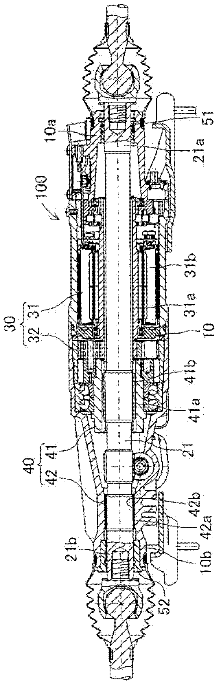
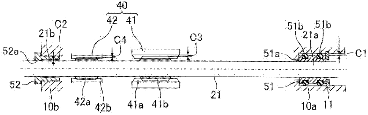
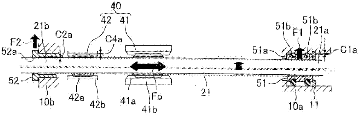
[0019] Below, with reference to the embodiment of the rear wheel steering device disclosed herein Figure 1 to Figure 3 , illustrating a vehicle rear wheel steering device according to an embodiment disclosed herein. Unless otherwise stated, the left and right sides mentioned in the specific instructions are respectively described Figure 1 to Figure 3 The left and right sides in , and the axial direction represent the axial direction of the connecting rod 21 . like figure 1 As shown, the rear wheel steering device 100 according to this embodiment includes: a housing 10, which is configured to be installed on the vehicle body; a connecting rod 21, which is non-rotatable relative to the housing 10, and supported in an axially movable manner, and the connecting rod 21 Each of the opposite ends 21a, 21b of the vehicle is connected to the corresponding rear wheels on the left and right sides of the vehicle; become the driving force in the axial direction of the connecting rod 2...


PUM


Abstract

A vehicular rear wheel steering device (100) includes a housing (10), a rod (21) being non-turnable with respect to the housing (10) and movably supported in an axial direction of the rod (21), and a conversion mechanism (40) arranged between the rod (21) and the housing (10) to convert a rotation of a rotational drive device (30) to a drive force in the axial direction. The housing (10) includes a tubular first bush (51) disposed at a first end (10a) and a tubular second bush (52) at a second end (10b). Each bush (51, 52) is slidably engaged to an outer periphery of the rod (21) and supports the rod (21) to be movable in the axial direction. A rod supporting rigidity of the first bush (51) is lower compared to that of the second bush (52). The first bush (51) is arranged with an elastic body (51b) that deforms in a radial direction of the rod (21). The second bush (52) is arranged with an inner periphery protrusion (52a) at which the rod (21) tilts.

Description

technical field [0001] The present invention generally relates to a vehicle rear wheel steering device. Background technique [0002] A vehicle rear wheel steering device is disclosed in JP2009-113730A (hereinafter referred to as Patent Document 1). In the vehicle rear wheel steering device disclosed in Patent Document 1: at the spline structure of the conversion mechanism (which includes a spline protrusion formed on the link and a spline groove formed on the housing), the first link of the link The second end of the connecting rod is non-rotatable relative to the casing, but is supported movable in the axial direction; and the second end of the connecting rod is non-rotatable relative to the casing, but is supported movable axially through a predetermined gap in the radial direction of the connecting rod. [0003] In the vehicle rear wheel steering device disclosed in Patent Document 1, in addition to a predetermined gap defined in the radial direction of the connecting r...

Claims


Application Information

Patent Timeline
Patent Type & Authority Applications(China)
IPC IPC(8): B62D5/04B62D7/16
CPCB62D3/06B62D3/12B62D5/0427B62D7/1581
Inventor 藤范洋一景山裕充田中肇林兼司西村公一永田健次郎山口直树种子田彰哉
Owner AISIN SEIKI KK
Why Eureka
Try Eureka