Storage box of cooling liquid of automobile

A technology of coolant and storage tank, which is applied to the cooling of the engine, engine components, machine/engine, etc., can solve the problems of increased impact of the collision body and reduced deformation stroke of the hood panel, and achieve the effect of increasing the deformation stroke

A technology of coolant and storage tank, which is applied to the cooling of the engine, engine components, machine/engine, etc., can solve the problems of increased impact of the collision body and reduced deformation stroke of the hood panel, and achieve the effect of increasing the deformation stroke

CN102628394BActive Publication Date: 2014-08-06NISSAN MOTOR CO LTD

Image

  • Storage box of cooling liquid of automobile
  • Storage box of cooling liquid of automobile
  • Storage box of cooling liquid of automobile

Examples


Embodiment Construction

[0021] Hereinafter, embodiments of the present invention will be described in detail with reference to the drawings.

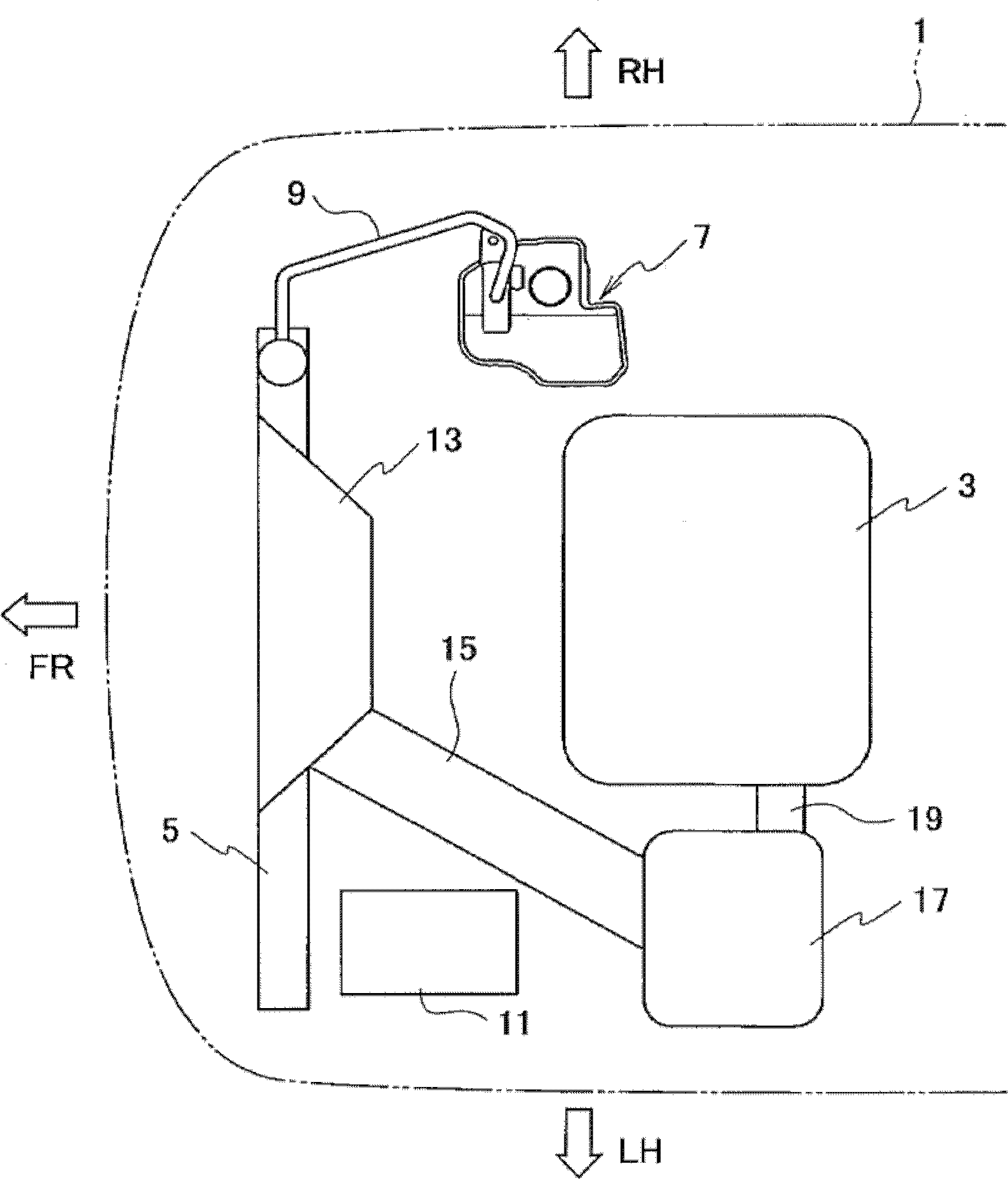
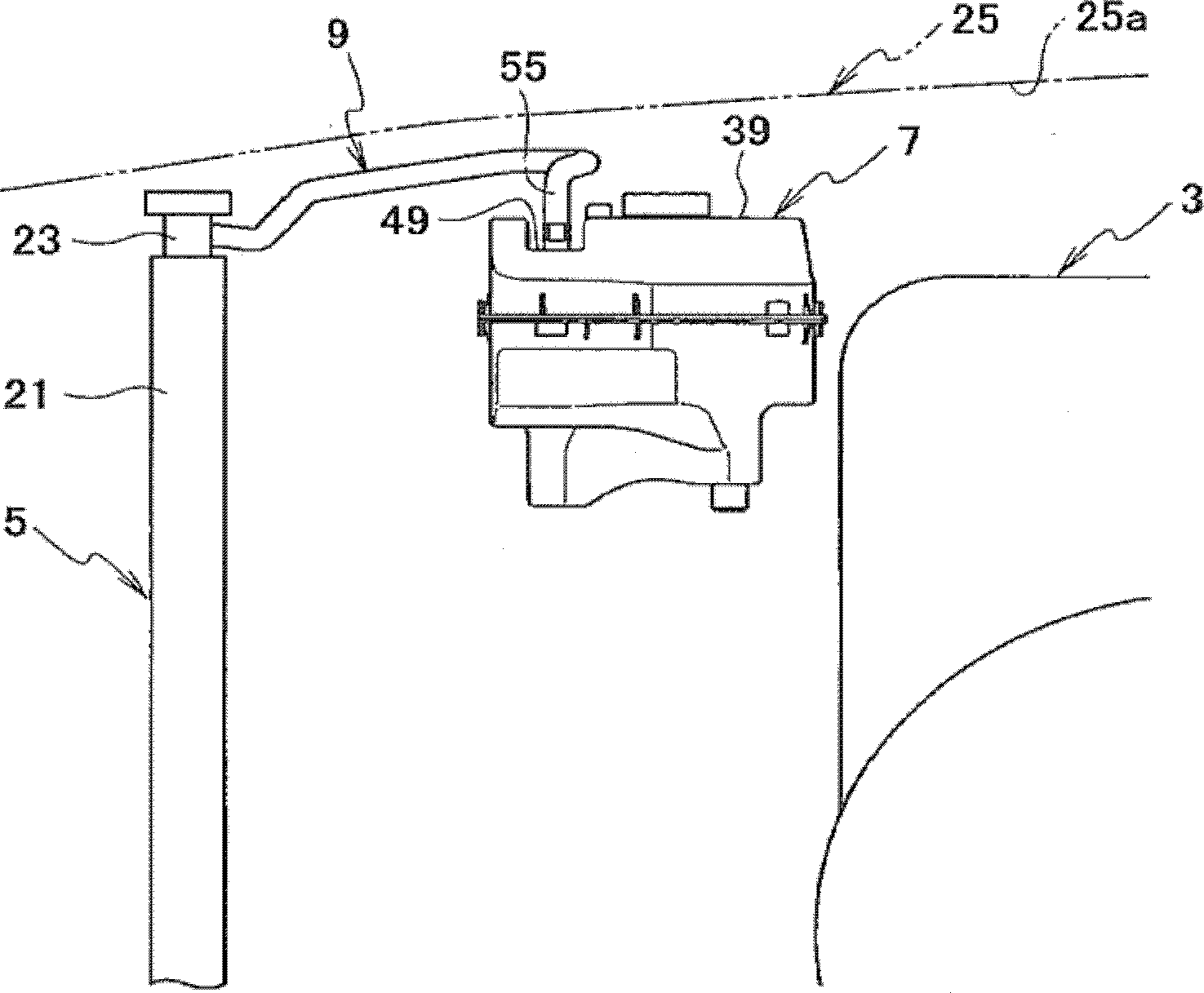
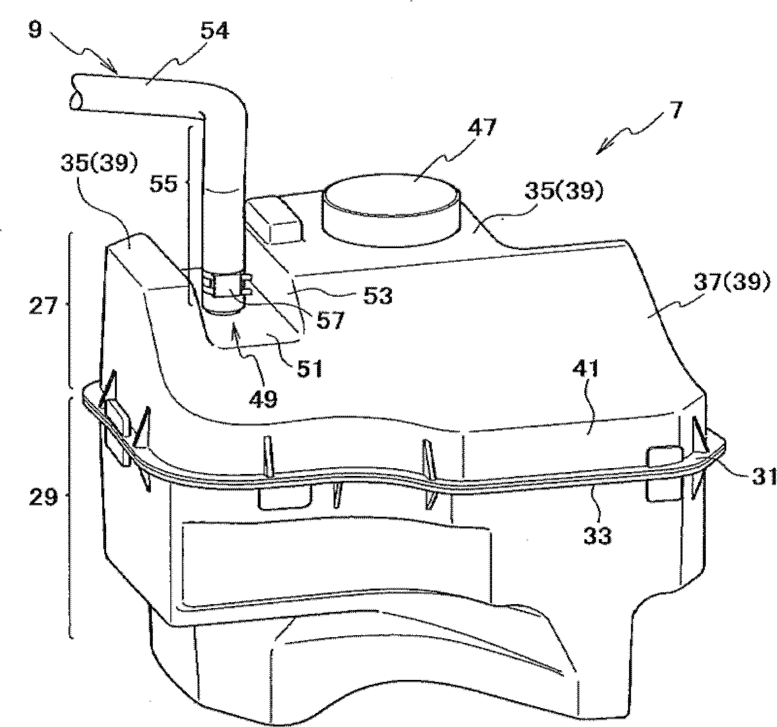
[0022] like figure 1 , 2 As shown, an engine 3 is disposed in the center of an engine compartment 1 at the front of the vehicle. In addition, a flat radiator 5 is arranged in the vehicle width direction at a front portion in the engine room 1 , and a tank 7 is arranged behind the radiator 5 on the right side. The radiator 5 and the tank 7 are connected via an overflow pipe 9 . Further, a battery 11 is arranged behind the left side of the radiator 5 , and an intake duct 13 for taking in traveling air is arranged above the radiator 5 . The intake passage 13 is connected to an air filter 17 at the left end via a passage 15 , and the air filter 17 is connected to the engine 3 via a pipe 19 . As a result, the travel air taken in from the air intake port 13 is purified by the air filter 17 and then sent to the engine 3 .

[0023] In addition, in figure 1 In th...


PUM


Abstract

The present invention provides a coolant tank for automobiles that can fully ensure the deformation stroke of the hood panel when a load is input downward from a collision body to the hood panel. The storage box (7) of the present invention is arranged adjacent to the lower part of the hood panel (25). A recessed portion (49) recessed downward is formed in a part of the upper surface (39) of the tank (7), and a joint portion (43) connected to the overflow pipe (9) is protruding from the recessed portion (49).

Description

technical field [0001] The present invention relates to a storage tank for coolant of an automobile. Background technique [0002] Currently, a radiator of an automobile is connected to a tank via an overflow pipe (for example, refer to Patent Document 1). The tank is configured such that when the coolant expands at high temperature, the coolant overflows from the tank of the radiator and flows into the tank through the overflow pipe. [0003] Patent Document 1: (Japanese) Patent No. 3562009 [0004] However, if a junction part is provided on the upper surface of the tank and the junction part is connected to the overflow pipe, the vertical distance between the hood panel and the junction part will be reduced. Then, when a load is input downward to the hood panel from the collider, the hood panel deforms and hits the junction, so there is a possibility that the deformation stroke of the hood panel becomes smaller and the impact on the collider increases. The problem. Co...

Claims


Application Information

Patent Timeline
06 Aug 2014
Publication
CN102628394B
IPC
F01P11/00
Inventors
中川卓之; 高松范夫