Aircraft inertial navigation combination double-shaft self-calibration device

An aircraft and self-calibration technology, applied in the field of inertial navigation, can solve the problems of complex test process, limited environmental adaptability, and low degree of automation, and achieve the effects of avoiding unreliable factors, saving logistics guarantee costs, and high degree of automation

Active Publication Date: 2012-08-08
THE GENERAL DESIGNING INST OF HUBEI SPACE TECH ACAD
View PDF6 Cites 21 Cited by
  • Summary
  • Abstract
  • Description
  • Claims
  • Application Information

AI Technical Summary

Problems solved by technology

[0003] At present, the aircraft inertial group calibration process is complicated, and the aircraft inertial group needs to be disassembled, and the calibration test is performed on a third-party special test equipment.
The testing process is complex and requires manual intervention
However, the existing single-axis and dual-axis calibration devices for land and marine inertial units have limited environmental adaptability and cannot be used on aircraft.
[0004] Judging from the published information, most of the single-axis or dual-axis modulation devices for land and marine inertial sets are limited to theoretical research, and these devices mainly have the following limitations, which restrict their application on aircraft
First, single-axis modulation devices often cannot complete the calibration of all parameters of the inertial group solely relying on the degrees of freedom of their own shaft system
Second, the existing single-axis or dual-axis modulation devices have relatively low requirements for locking and releasing reliability, and the degree of automation is not high
Third, in this type of device, especially in the dual-axis rotary device, the slip ring method is often used for wiring, and there is relative sliding between the slideway and the contact point, and the reliability of the inertial group cannot be guaranteed in the shock and vibration environment during the flight of the aircraft. Work

Method used


Image

  • Aircraft inertial navigation combination double-shaft self-calibration device
  • Aircraft inertial navigation combination double-shaft self-calibration device
  • Aircraft inertial navigation combination double-shaft self-calibration device

Examples


Embodiment Construction

[0031] The present invention will be further described in detail below in conjunction with the accompanying drawings and specific embodiments.

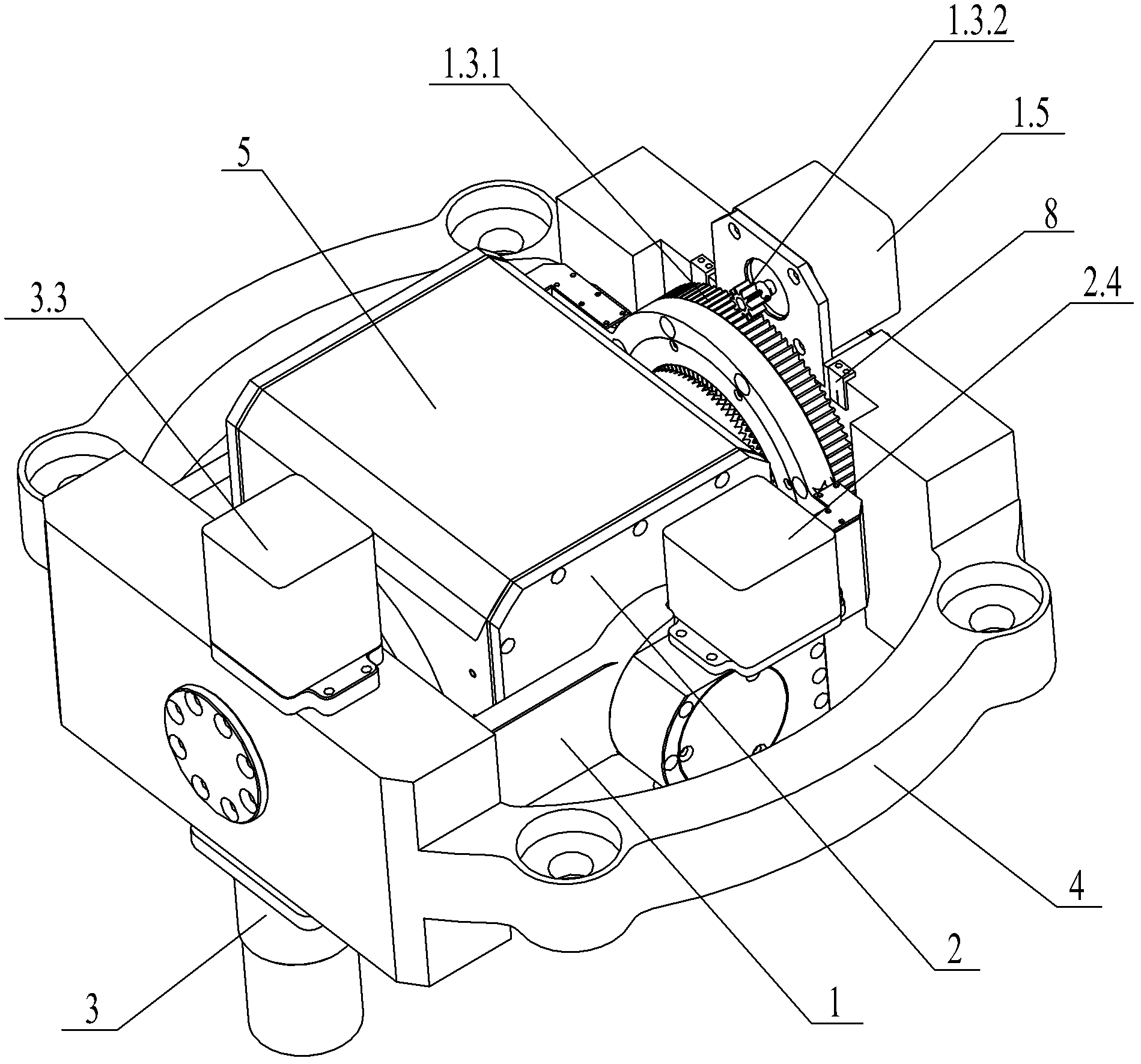
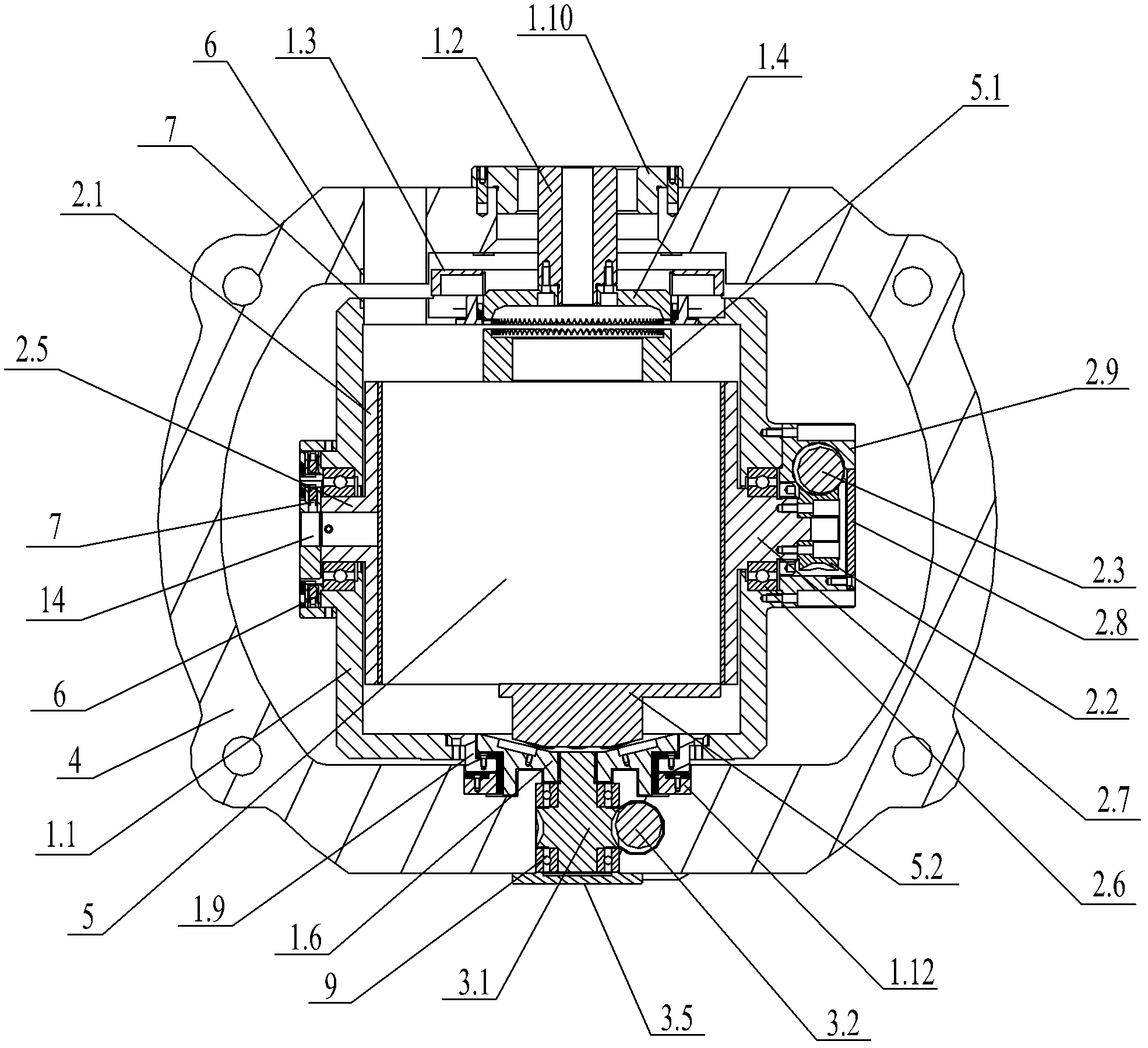
[0032] figure 1 , 2 The shown aircraft inertial group dual-axis self-calibration device includes a base 4 with a ring structure, an outer frame shaft system 1 installed on the base 4, and an inner frame shaft system installed on the outer frame shaft system 1 2. The aircraft inertial group 5 connected to the inner frame shaft system 2 and the automatic locking device 3 installed on the base 4 . The outer frame shaft system 1 includes an outer frame 1.1, and the two longitudinal sides of the outer frame 1.1 are divided into a sliding end and a locking end.

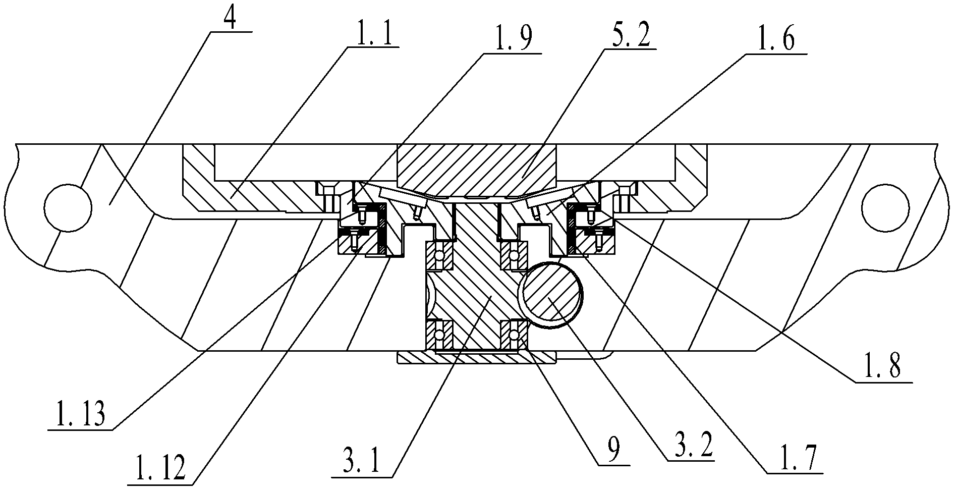
[0033] combine image 3 , the sliding end of the outer frame 1.1 is fixedly connected with the outer frame shaft hole adapter bracket 1.9, the outer frame shaft hole adapter bracket 1.9 is provided with a jacking nut 1.6, and the outer periphery of the jacking nut 1.6 is movably...


PUM


Abstract

The invention discloses an aircraft inertial navigation combination double-shaft self-calibration device, which comprises a pedestal, an outer frame shaft system and an automatic locking device mounted on the pedestal, an inner frame shaft system mounted on the outer frame shaft system, an aircraft inertial navigation combination connected to the inner frame shaft system, and infrared sensors for determining the rotation positions of the outer and inner frame shaft systems. The outer frame shaft system includes an outer frame, the two sides of which in the longitudinal direction are a sliding end and a locking end respectively. The inner frame shaft system includes inner frames arranged on two sides of the aircraft inertial navigation combination. The inner frames on the two sides are respectively provided with an inner frame shaft and an inner frame supporting rod that are respectively mounted on the lateral two sides of the outer frame by rolling bearings. The automatic locking device consists of a composite screw installed on the pedestal through angular contact bearings. The longitudinal two sides of the aircraft inertial navigation combination are equipped with a movable fluted disc and a push rod respectively. By means of automatic rotation of the inner and outer frame shaft systems, the device of the invention achieves self-calibration of the inertial navigation combination in the aircraft, and guarantees reliable strapdown between the aircraft inertial navigation combination and the aircraft through the automatic locking device.

Description

technical field [0001] The invention belongs to the field of inertial navigation, in particular to an aircraft inertial set dual-axis self-calibration device. Background technique [0002] An inertial navigation system usually consists of an inertial measurement device, a computer, a control display, etc. Among them, the inertial measurement device includes an accelerometer and a gyroscope, also known as an inertial navigation combination (abbreviated as an inertial group). The 3 degrees of freedom gyroscopes are used to measure the 3 rotational movements of the aircraft; the 3 accelerometers are used to measure the acceleration of the 3 translational movements of the aircraft. The strapdown inertial navigation system is simple in structure, small in size, and easy to maintain. It is directly installed on the aircraft through the inertial group to complete the guidance and navigation tasks. Therefore, the aircraft inertial set is the core of the aircraft control system and...

Claims


Application Information

Patent Timeline
Patent Type & Authority Applications(China)
IPC IPC(8): G01C25/00
Inventor 王亚军周海李春权曾军高孙刚文
Owner THE GENERAL DESIGNING INST OF HUBEI SPACE TECH ACAD
Why Eureka
Try Eureka