Current collector for manipulator

A manipulator and collector technology, applied in the field of collectors for manipulators, can solve problems such as being unsuitable for manipulator applications, and achieve the effect of reducing electrical failures and ensuring cleanliness.

Active Publication Date: 2012-08-08
CHANGSHU HUIYI MECHANICAL&ELECTRICAL CO LTD
View PDF6 Cites 6 Cited by
  • Summary
  • Abstract
  • Description
  • Claims
  • Application Information

AI Technical Summary

Problems solved by technology

This current collector is not suitable for robotic applications

Method used


Image

  • Current collector for manipulator
  • Current collector for manipulator
  • Current collector for manipulator

Examples


Embodiment

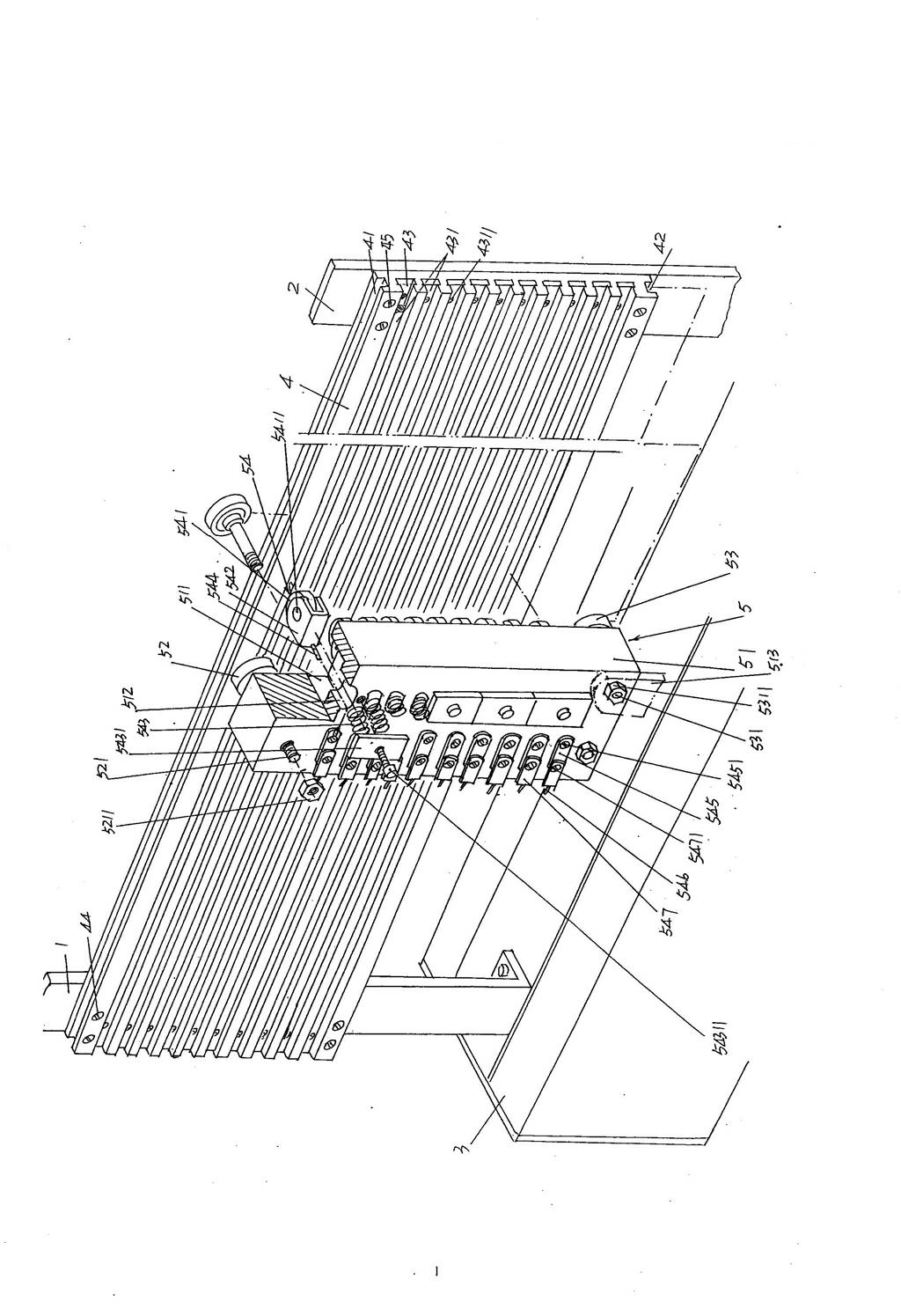
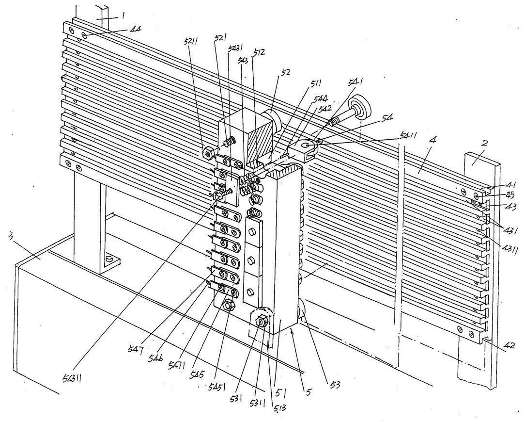
[0013] See figure 1 , shows the cross arm 3 of the manipulator. According to the known technology, the execution parts of the manipulator are usually installed on the cross arm 3 . A first support 1 and a second support 2 are fastened longitudinally parallel to each other on the transverse arm 3 . One end (the left end in the figure) of a conductive strip fixing plate 4 is fixed on the first support 1 with a first screw 44 , and the other end (the right end in the figure) is fixed on the second support 2 with a second screw 45 . An upper roller groove 41, a lower roller groove 42 and a group of conductive strip grooves 43 between the upper and lower roller grooves 41, 42 are formed on the side of the conductive strip fixing plate 4 facing the current collector 5 described below. Depend on figure 1 As shown, the upper and lower roller grooves 41, 42 and the conductive strip groove 43 all pass through from one end (left end) to the other end (right end) of the length dire...


PUM


Abstract

The invention discloses a current collector for a manipulator, and belongs to the technical field of a feeding device of the manipulator. The current collector comprises a first bracket, a second bracket, a conducting strip fixing plate and a current collection device, wherein the first bracket and the second bracket are arranged on a cross arm of the manipulator; one end of the conducting strip fixing plate is fixed to the first bracket, and the other end of the conducting strip fixing plate is fixed to the second bracket; an upper roller groove, a lower roller groove and a group of conductive strip grooves are constructed on one side of the conductive strip fixing plate facing to the current collection device; the group of conductive strip grooves are spaced away from each other and are positioned between the upper roller groove and the lower roller groove; a conductive strip which is electrically connected with an external power supply is fixed in each conductive strip groove; all the upper roller groove, the lower roller groove and the group of conductive strip grooves run through from one end of the conductive strip fixing plate in the length direction to the other end; and the current collector is in sliding fit with the upper roller groove and the lower roller groove and is in sliding fit with the conductive strip grooves in a contact state with the conductive strips. The current collector has the advantages of capability of reducing the electrical failure, simple overall structure and capability of guaranteeing a clean effect of a set of manipulator.

Description

technical field [0001] The invention belongs to the technical field of power feeding devices for manipulators, and in particular relates to a collector for manipulators, which is connected to a manipulator guide bar base and moves with the movement of the manipulator guide bar base to provide power for executive parts of the manipulator. Background technique [0002] The executive components of the manipulator in the prior art are fed by redundant power supply wires to provide working power. During the movement of the manipulator, the wires are pulled along with it, which is prone to wear or even breakage, affecting the normal work of the manipulator. And lengthy and numerous wires also affect the tidy effect of the manipulator. [0003] A large amount of technical information on current collectors can be found in published Chinese patent documents. For example, CN260188Y recommends "a current collector", and CN201435521Y introduces "a current collector", etc. Such current ...

Claims


Application Information

Patent Timeline
IPC IPC(8): H01R41/00B25J19/00
Inventor 朱建惠
Owner CHANGSHU HUIYI MECHANICAL&ELECTRICAL CO LTD
Why Eureka
Try Eureka