
Plate conveyer table

A transfer table and plate technology, which is applied in the direction of transportation, packaging, rollers, etc., can solve the problem that the plate cannot be shifted or transferred

Inactive Publication Date: 2012-08-15
新疆新能钢结构有限责任公司
View PDF10 Cites 8 Cited by
  • Summary
  • Abstract
  • Description
  • Claims
  • Application Information

AI Technical Summary

Problems solved by technology

Since the hoisting starting area and the target area are not on the same horizontal line, there is no crane that can realize both horizontal and vertical two-way movement at the same time in the market, so it is impossible to realize the necessary displacement or transfer of plates on different horizontal lines only by crane hoisting

Method used


Image

  • Plate conveyer table
  • Plate conveyer table
  • Plate conveyer table

Examples


Embodiment Construction

[0013] The preferred embodiments of the present invention will be described below in conjunction with the accompanying drawings. It should be understood that the preferred embodiments described here are only used to illustrate and explain the present invention, and are not intended to limit the present invention.

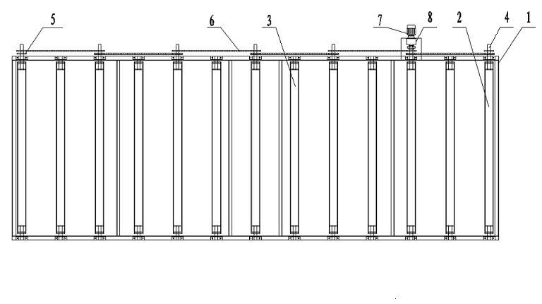
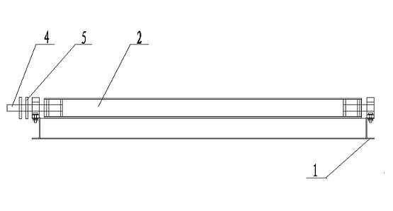
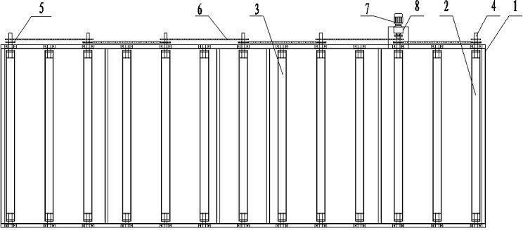
[0014] Such as figure 1 , figure 2 As shown, the plate transfer platform includes a frame 1, several rollers and a power device, and the frame is welded by 20# channel steel. The rollers are divided into powered roller 2 and non-powered roller 3, the powered roller 2 and the non-powered roller 3 are arranged at intervals, both ends of the roller are fixed on the frame 1 through the supporting shaft 4 and bearings, and the powered roller The support shaft 4 at one end of the cylinder 2 protrudes from the outside of the frame 1, and a sprocket 5 is arranged on the support shaft, and the two adjacent powered rollers 2 are driven by a chain 6 and a sprocket 5. The pow...


PUM


Abstract

The invention discloses a plate conveyer table. The plate conveyer table comprises a rack, a plurality of rollers and a power device; the rollers comprise power rollers and unpowered rollers; the power rollers and the unpowered rollers are arranged at intervals; the two ends of the rollers are fixed on the rack by supporting shafts and bearings; the supporting shaft at one end of the power roller protrudes out of the outer side of the rack and the supporting shaft is provided with chain wheels; the adjacent two power rollers are driven by chains and chain wheels; the power device comprises a motor and a speed reducer; the motor is connected with the speed reducer; and then the motor and the supporting shaft of one of the power rollers are driven by the chains and the chain wheels. According to the plate conveyer table, the rotary circular motion of the rollers drives the plates on the rollers to carry out linear motion; and the conveying of the plates is realized on the condition that the starting zone and the target zone are not on the same horizon line in the conveying process.

Description

technical field [0001] The invention relates to a plate transfer platform, which belongs to the field of transportation devices. Background technique [0002] At present, in the production of towers (steel structure products), the steel plates must be shifted or transferred due to the process. After the steel plates are processed in one work area, the steel plates need to be hoisted by a crane and hoisted to another work area for processing. Since the hoisting starting area and the target area are not on the same horizontal line, there is no crane that can realize both horizontal and vertical two-way movement at the same time in the market, so it is impossible to realize the necessary displacement or transfer of plates on different horizontal lines only by crane hoisting . Contents of the invention [0003] The technical problem to be solved by the present invention is to overcome the existing defects and provide a plate transfer platform to realize plate transfer when th...

Claims


Application Information

Patent Timeline
IPC IPC(8): B65G13/07
Inventor 周晓明徐成春张勇张雪江武迎峰肖炳花刘春雨夏红
Owner 新疆新能钢结构有限责任公司
Learn More