Drip irrigation tape withdrawing machine

A technology of recycling machine and drip irrigation belt, applied in the field of drip irrigation belt recycling machine, can solve the problems of time-consuming, troublesome, laborious, etc., and achieve the effect of improving recycling efficiency

Inactive Publication Date: 2012-08-15
袁庆龙
View PDF6 Cites 6 Cited by
  • Summary
  • Abstract
  • Description
  • Claims
  • Application Information

AI Technical Summary

Problems solved by technology

[0002]Our country is a big agricultural country, and it is also a country with serious water shortage. Therefore, water-saving drip irrigation technology is being used more and more widely, and it is also used in farmland every year There are a lot of drip irrigation belts left in the garden, which need to be recycled and reused. In the past, it was done manually, which was time-consuming and laborious. The drip irrigation belt recycling machine disclosed in Chinese patent CN 201309780Y is equipped with a transmission shaft connected to the tractor at the front end of the frame. , There is a shaft on the frame, and a take-up wheel is arranged on the shaft. The take-up wheel is divided into left and right parts. The two parts of the take-up wheel are connected to each other through a tapered sleeve. When in u

Method used


Image

  • Drip irrigation tape withdrawing machine
  • Drip irrigation tape withdrawing machine
  • Drip irrigation tape withdrawing machine

Examples


Embodiment 1

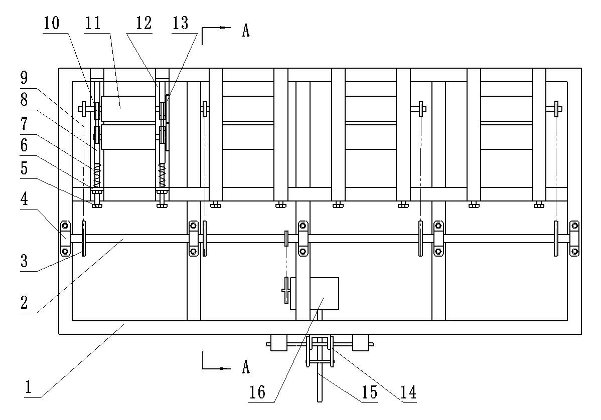
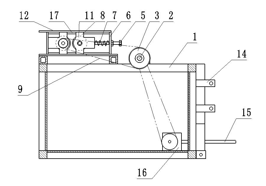
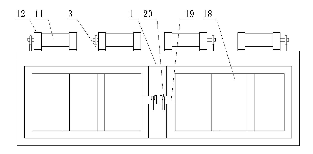
[0021] Example 1: Refer to Figure 1 ~ Figure 3 In order to invent the structural diagram of the implementation example 1, the lower part of the rack 1 forms a box, and there is a suspension frame 14 at the front end of the rack 1.The drive shaft 15 is connected to the power connection of the tractor. At the upper end of the rack 1, there is an organic shaft 2. The axis 2 connects to the gearbox 16 through a chain.There are also roller bracket 12. There are 4 groups in the roller brackets in this embodiment. There are two roller wheels 11 on each group of roller brackets. There is a rolling wheel bearing seat 8 at both ends of the roller 11.There are skating 10, sliding 10 cards on the sliding rail 17 on the roller bracket 12, can be moved around the slide rail 17, and there is a baffle 6 on the roller bracket 12 on the rolling wheel 11.There is a bolt 5 on the Board 6, and there is a spring 7 between the bolt 5 and the roller wheel bearing seat 8. Adjust the bolt 5 to adjust the s...

Embodiment 2

[0022] Example 2: Refer to Figure 4 ~ Figure 5 For the structural diagram of the embodiment 2 of the invention 2, compared with the embodiment 1, the difference between the embodiment 2 and the embodiment 1 is that the embodiment 2 sets the front scrape 25 and the back scraping on the front and rear sides of the roller.The end of the mud board 24, the end of the rear scraper 24 is fixed on the roller bracket 12, the other end is bent down the edge of the wheel, one end of the front scrape 25 is also bent down to the edge of the other roller, the front scrape 25 25On the other end of the nail ring 23, the nail 21 is set on the adjustment board 27, and there is a regulating slot 28 in the middle of the adjustment board 27. The fastener bolt 22 is connected to the roller bracket 12 in the adjustment slot 28.The position of the adjustment board 27 makes the front scrape 25 close to the edge of the roller. There is a tape spring 26 at the front end of the front mud 25, which can make t...

Embodiment 3

[0023] Example 3: Refer to Figure 6 ~ Figure 8 For the structural diagram of the embodiment 3 of the present invention, compared with the embodiment 2, the difference between the embodiment 3 and the embodiment 2 is that in the embodiment 3 set the guide band 33 at the back end of the rack 1, at the back end of the rack 1, at the back end of the rack 1, at the back end of the rack 1, at the back endThe guide strap 33 is connected with a tube 31, and the tube 31 has a guide band ring 32. You can guide the drip irrigation band into the box through the roller. In order to adjust the position of the tube 31, it is also set on the tube 31 and also set it on the tube 31.There are screws 34. There are skids 29 at the front and rear ends of each group of roller brackets, and 29 slide 29 sets are on the rack 1. A adjustable bolt 30 is also set on the sliding cover 29, which can adjust the position of the roller bracket.


PUM


Abstract

The invention discloses a drip irrigation tape withdrawing machine, which comprises a framework (1), a suspension bracket (14), a gearbox (16), a transmission shaft (15) and a crankshaft (2). A roller support (12) is arranged on the framework (1), rollers (11) are disposed in the roller support (12), each group of rollers includes two rollers, and at least one roller (11) in each group can move on the roller support (12) and is provided with a spring (7) used for pushing the roller (11) to the other roller (11) in the group. The distance between the two rollers in each group can be automatically adjusted, squeezing force between the two rollers in each group can also be adjusted, and accordingly a drip irrigation tape cannot be broken when withdrawn. Compared with the prior art, the drip irrigation tape withdrawing machine can replace a manual drip irrigation tape withdrawing mode, and withdrawing efficiency of drip irrigation tapes can also be improved greatly.

Description

Technical field [0001] The invention involves a drip irrigation recycling machine. Background technique [0002] my country is a large agricultural country and a country with severe water shortage. Therefore, water -saving drip irrigation technology is also being used more and more widely. Every year, a large number of drip irrigation belts are left in farmland. They are all done by manual, time -consuming and laborious. The drip irrigation recyclable recycling machine opened by the Chinese patent CN 201309780Y has a transmission shaft connecting the tractor at the front of the rack. The rotor, the ribbon is divided into the left and right parts, and the two parts are put together by the cone -shaped sleeve. When used, the rack is hung on the tractor. After the roll is on the rotor, after the drip irrigation belt is filled, remove the rotor, and then remove the drip irrigation band to solve the problem of the mechanical recycling of the drip irrigation belt, which greatly improve...

Claims


Application Information

Patent Timeline
IPC IPC(8): B65H75/42
Inventor 袁庆龙
Owner 袁庆龙
Why Eureka
Try Eureka