Tunnel back reflection illuminating system setting method based on train speed control and train distance keeping

A technology of vehicle speed control and lighting system, applied in the directions of roads, roads, road signs, etc., can solve the problems of reduced speed control effect, low illumination and contrast, limited effect, etc., to improve the ability to confirm the distance between vehicles and improve the instantaneous perception speed , the effect of improving distance perception

Inactive Publication Date: 2012-08-15
WUHAN UNIV OF TECH
View PDF3 Cites 40 Cited by
  • Summary
  • Abstract
  • Description
  • Claims
  • Application Information

AI Technical Summary

Problems solved by technology

However, due to the low illumination and contrast in the tunnel, it is difficult for the driver to find the ordinary traffic engineering facilities in the tunnel, and the accident data also shows that their effect is limited
At the same time, the existing tunnel lighting mainly focuses on tunnel lighting energy-saving control, intelligent lighting control system, tunnel lighting settings combining natural light and artificial light, etc., and less research is based on traffic accidents, which also leads to high setup and operating costs. Traffic safety and benefits Mismatch
At the same time, the existing speed perception improvement method based on visual optical flow rate lacks research on the sense of direction and distance, which also leads to a decrease in sensitivity, reduced speed control effect, and even retaliatory acceleration after the driver is familiar with local information.

Method used


Image

  • Tunnel back reflection illuminating system setting method based on train speed control and train distance keeping
  • Tunnel back reflection illuminating system setting method based on train speed control and train distance keeping
  • Tunnel back reflection illuminating system setting method based on train speed control and train distance keeping

Examples


Embodiment Construction

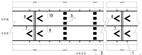
[0032] 1) Clean the side walls and road surface of the tunnel first, and paint the side walls, curb façade marking lines 2 (red and white) and roadside raised road signs 1;

[0033] 2) Install the multi-layer contour marking 3 on the tunnel side wall from bottom to top, and draw the vertical marking line 4 on the side wall extending to the roof of the cave, and set the horizontal illusion marking line 5 on the road surface of the tunnel;

[0034] 3) Draw two white folded lines 6 on the road surface according to the national standard (with a distance of 5m), and set two horizontal vibration markings 7 between the folded lines, and set white folded lines 8 at the same position on the side wall of the tunnel as in the longitudinal direction of the road surface;

[0035] 4) Draw lane boundary lines 9 and lane edge lines 10 on the tunnel pavement, and install cave roof lamps 11.

[0036] Precautions:

[0037] 1) This method is suitable for low-illumination expressway tunnels and i...


PUM


Abstract

The invention discloses a tunnel back reflection illuminating system setting method based on train speed control and train distance keeping. The method comprises the steps of: arranging tunnel side walls, red and white facade marked lines on lower edges of curbs, and road surface raised pavement markers on road sides to form a space high-frequency vision information stream; secondly, arranging a plurality of layers of outline markers on the tunnel side walls at intervals of 25-50m in an advancing direction, arranging side wall vertical marked lines and extending to the top of a cave, transversely arranging transverse wrong vision marked lines on the road surface to form a space medium-frequency vision information stream; and then arranging two white folded lines and vibration marked lines on the road surface every 3 medium-frequency transverse marked lines at intervals of 100-200m in the advancing direction, and arranging two white folded lines on the side walls to form a space low-frequency vision information stream. Multiple channels of frequency vision systems are made of a high-strength back reflection material, so that a back reflection illuminating system is formed, perception of velocity and perception of distance of a driver are effectively improved, thus the integration of tunnel illuminating benefit and tunnel safety is achieved. The tunnel back reflection illuminating system setting method can be applied to tunnel illumination of low-light expressways with speed limit of 60-80km / h and traffic safety facility improvement.

Description

[0001] technical field [0002] The invention relates to a setting method of a tunnel retroreflective lighting system that improves the driver's vehicle speed control and vehicle distance maintenance capabilities, so as to realize the coordination of tunnel lighting energy saving and tunnel traffic safety benefits. Background technique [0003] The operating lighting of the tunnel section is insufficient, speeding is common in the tunnel, and accidents of rear-end collisions and side walls are frequent. The "JTJ026.1-1999 Design Code for Ventilation and Lighting of Highway Tunnels" promulgated in 1999 and the "JTG / T D 71-2004 Code for Design of Road Tunnel Traffic Engineering" promulgated in 2004 have made the configuration of electromechanical facilities of road tunnels in my country reach a very high level. Level. For highway tunnels, according to my country's national standards, the lighting load should not be less than 60kW per kilometer of tunnel extension. Taking the ...

Claims


Application Information

Patent Timeline
Patent Type & Authority Applications(China)
IPC IPC(8): E01F9/00E01F9/015E01F9/08E01F9/053E01F9/524E01F9/529E01F9/541E01F9/576
Inventor 杜志刚万红亮蒋旭黄发明刘启远陶鹏鹏
Owner WUHAN UNIV OF TECH
Why Eureka
Try Eureka