Hydraulic shock absorber and damping force generator

A technology of hydraulic buffering and generating device, applied in gas-liquid shock absorbers, springs, shock absorbers, etc., can solve the problems of disordered damping force, difficult oil flow, and decreased responsiveness.

Inactive Publication Date: 2012-08-15
SHOWA CORP
View PDF1 Cites 2 Cited by
  • Summary
  • Abstract
  • Description
  • Claims
  • Application Information

AI Technical Summary

Problems solved by technology

However, if a flange nut is used, the diameter of the base point where the damping force generation valve deforms is larger than that of the valve seat, so the valve becomes difficult to deform, making it difficult for the oil to flow smoothly.
As a result, the damping force of the hydraulic shock absorber may be disturbed and the responsiveness may be reduced.

Method used


Image

  • Hydraulic shock absorber and damping force generator
  • Hydraulic shock absorber and damping force generator
  • Hydraulic shock absorber and damping force generator

Examples


Embodiment Construction

[0033] Hereinafter, embodiments of the present invention will be described in detail with reference to the drawings.

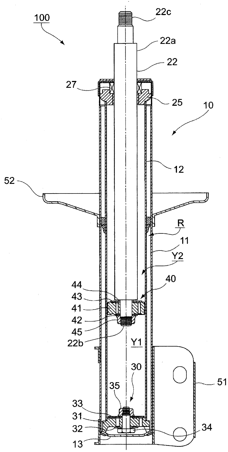
[0034] figure 1 It is a figure which shows the schematic structure of the hydraulic shock absorber 100 which concerns on an embodiment.

[0035] The hydraulic shock absorber 100 of the embodiment is a multi-cylinder hydraulic shock absorber constituting a part of a strut type suspension.

[0036] Such as figure 1 As shown, the hydraulic buffer device 100 is equipped with a hydraulic cylinder 10, and the hydraulic cylinder 10 has: a thin-walled cylindrical outer cylinder 11; a thin-walled cylindrical inner cylinder 12, which is accommodated in the outer cylinder 11; and a bottom cover 13, which is closed The cylinder centerline direction of the cylindrical outer cylinder 11 (in figure 1 One end of the middle is the up and down direction). Hereinafter, the cylindrical centerline direction of the outer cylinder 11 is simply referred to as "centerline directio...


PUM


Abstract

A hydraulic shock absorber includes: a dividing member dividing a closed space and having a communicating passage for communicating divided spaces; a valve covering an open end of the communicating passage; a bolt penetrating through the dividing member and the valve; and a nut fastening the dividing member and the valve together with the bolt. The bolt or the nut has a head fitted with an industrial tool, and a base end arranged on a valve side beyond the head to contact with the valve and including an extending part extending outside an outer shape of the head in a radial direction, a facing part of the base end facing the valve comes into contact with the valve at a position inside an outermost end of the extending part in the radial direction, and an outer region outside a contact part does not come into contact with the valve.

Description

technical field [0001] The invention relates to a hydraulic buffer device and a damping force generating device. Background technique [0002] Suspension devices of vehicles such as automobiles are equipped with hydraulic shock absorbers using damping force generators in order to moderate vibrations transmitted from the road surface to the vehicle body during driving and improve ride comfort and handling. [0003] Furthermore, for example, the hydraulic shock absorber described in Patent Document 1 is configured as follows. That is, a hydraulic cylinder is constituted by a double-layered cylinder such as an inner cylinder on which the piston slides and an outer cylinder provided outside the inner cylinder, and the hydraulic shock absorber includes: A piston type slide valve (piston valve) device composed of a piston rod in the center; and a bottom valve (bottom valve) device composed of a damping force generating valve and the like and arranged at the bottom. In the piston...

Claims


Application Information

Patent Timeline
Patent Type & Authority Applications(China)
IPC IPC(8): F16F9/00F16F9/06F16F9/32
CPCF16F9/3485
Inventor 押江雄己松竹泰伯金子谦一郎
Owner SHOWA CORP
Why Eureka
Try Eureka