Movable valve hydraulic action system used for continuous adsorption switching equipment

A technology of adsorption exchange and hydraulic action, applied in mechanical equipment, valve operation/release devices, valve details, etc., can solve the problems of increased amount of regeneration fluid, easy wear of flat seals, easy wear of PTFE gaskets, etc. The effect of reducing assembly and manufacturing costs, reducing machining accuracy requirements, and increasing safety and reliability

Inactive Publication Date: 2013-08-14
工信华鑫科技有限公司
View PDF5 Cites 0 Cited by
  • Summary
  • Abstract
  • Description
  • Claims
  • Application Information

AI Technical Summary

Problems solved by technology

[0006] c) The plane seal is easy to wear, and there will be a phenomenon of cross-flow between the flow channels of each column;
[0007] d) The transmission and control are complex and energy-consuming;
[0008] e) High maintenance cost
[0009] We dissect, research and analyze foreign continuous ion exchange equipment, and think that the main reasons are: first, it is a flat seal, and the gasket is polytetrafluoroethylene. The flat seal of this material requires a lot of pressure to make the tetrafluoro gasket deform to a certain extent. The second is that the general processing accuracy is difficult to guarantee its tightness. Under pressure, the two-way steel lower valve plate of the porous distribution valve presses the PTFE gasket on the upper valve plate tightly, so that the PTFE gasket produces Micro-deformation, jamming into the valve hole, during the relative rotation process, the PTFE gasket is easy to wear, so that the material and liquid in each hole will leak to each other. This leakage is not easy to detect, so it is more harmful and easy to cause product damage Quality decline, eluent, regenerating fluid consumption increases, etc.; third, the imported flat seal continuous separation device is generally a problem of seal leakage, which is quite troublesome to replace or repair, and can only be repaired by disassembling the valve body completely.

Method used


Image

  • Movable valve hydraulic action system used for continuous adsorption switching equipment
  • Movable valve hydraulic action system used for continuous adsorption switching equipment

Examples


Embodiment Construction

[0033] In order to make the technical problems, technical solutions and beneficial effects solved by the present invention clearer, the present invention will be further described in detail below in conjunction with the accompanying drawings and embodiments. It should be understood that the specific embodiments described here are only used to explain the present invention, not to limit the present invention.

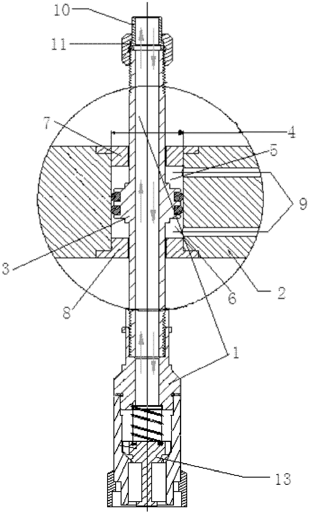
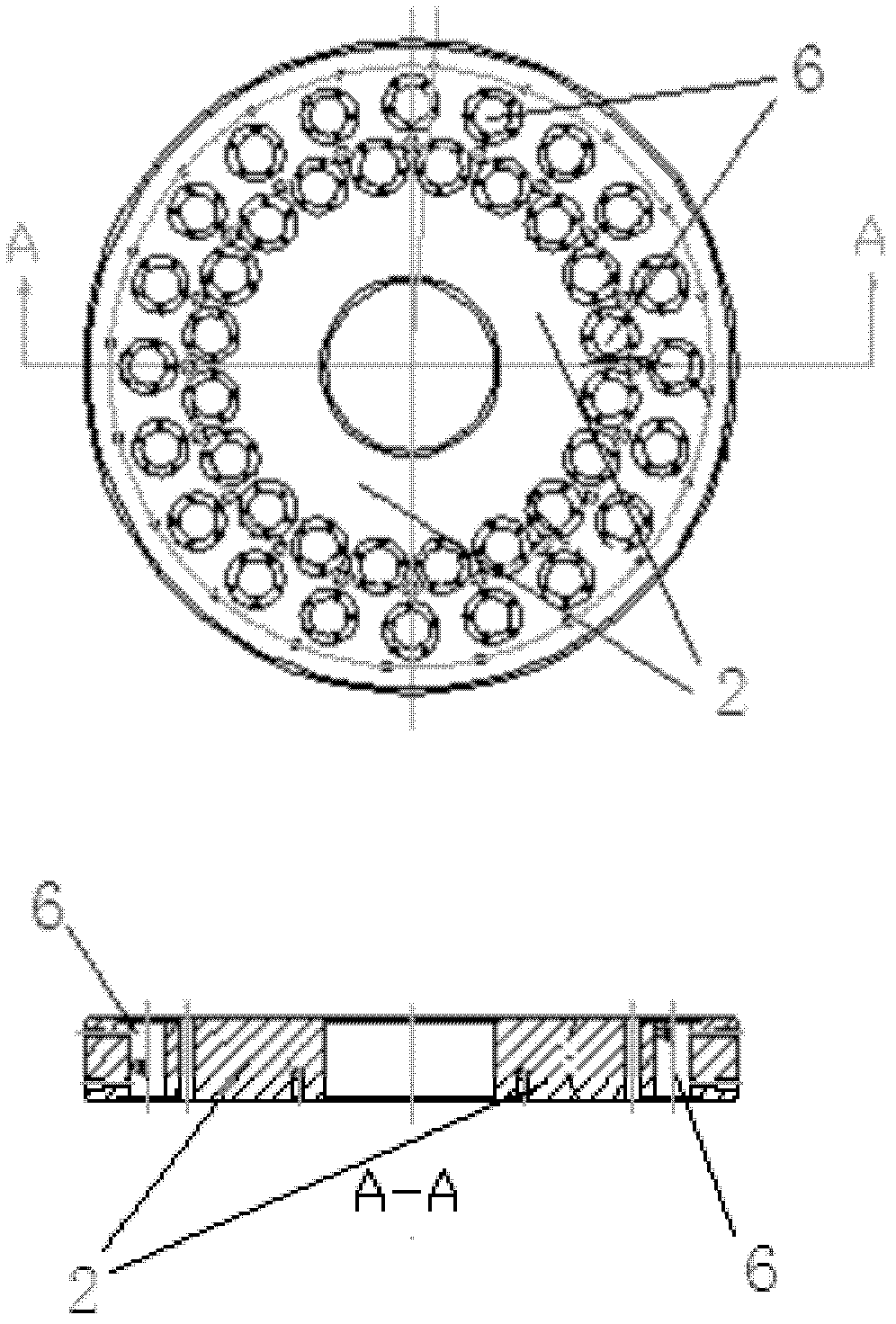
[0034] Such as figure 1 with figure 2 A movable valve hydraulic action system for continuous adsorption exchange equipment is shown, including a piston 3 arranged on the stem 1 of the movable valve and a cylinder hole 4 arranged on the fixed disk 2, and the piston 3 is located in the cylinder In the hole 4; the movable valve stem 1 on the upper and lower sides of the piston 3 and the cylinder hole 4 are installed in a sliding seal to form two upper and lower piston sealing chambers 5 / 6; the upper and lower two piston sealing chambers 5 / 6 are connected to the external...


PUM


Abstract

The invention discloses a movable valve hydraulic action system used for continuous adsorption switching equipment. The movable valve hydraulic action system comprise a piston and an oil cylinder hole, wherein the piston is arranged on the valve rod of a movable valve; the oil cylinder hole is arranged on a fixed tray; and the piston is arranged in the oil cylinder hole; the valve rod of the movable valve and the oily cylinder hole at the upper side and the lower side of the piston are arranged in a sliding seal way to form an upper piston sealing cavity and a lower piston sealing cavity; andthe upper piston sealing cavity and the lower piston sealing cavity are both communicated to an external hydraulic system. According to the movable valve hydraulic action system, the 'serial boat' effect that one fault in a ring can result in the breaking down of the whole boat which is caused by the integral movement of the hydraulic system of the traditional similar equipment is changed throughthe integrated designs of breaking up the whole into parts and combining two into one. According to the movable valve hydraulic action system used for the continuous adsorption switching equipment, the bias current phenomenon easily appearing in the traditional continuous ion exchange bed adsorption process can be effectively overcome, idle waste of parts of resin is avoided, and the resin use rate is low.

Description

technical field [0001] The invention relates to the technical field of highly refined electrowinning of heavy metals in hydrometallurgy, in particular to a hydraulic action system of a movable valve used in continuous adsorption exchange equipment. Background technique [0002] Continuous ion exchange is a world-recognized advanced separation technology. my country's continuous ion exchange equipment was introduced from Finland by a company in Xiamen around 2002. It is first applied in the purification of antibiotics and Vc in the pharmaceutical industry, and then gradually applied in biological extraction, food and beverage, chemical industry and environmental protection. However, the cost of the equipment is expensive, and it is difficult to popularize and apply it in hydrometallurgy. [0003] Disadvantages of foreign continuous ion exchange equipment: [0004] a) The structure is complex and the cost is high. The price of a continuous ion exchange equipment that can pr...

Claims


Application Information

Patent Timeline
Patent Type & Authority Patents(China)
IPC IPC(8): F16K31/122
Inventor 邱建宁徐纯理赵路李新华杨斗
Owner 工信华鑫科技有限公司
Why Eureka
Try Eureka