
Composite plane groove type condenser with high light condensation times and uniform condensation uniformity

A technology of light-gathering multiples and composite planes, applied in the direction of condensers, optics, instruments, etc., can solve problems such as inability to achieve uniform light-gathering, affect the normal use of battery panels, and enhance illumination

Inactive Publication Date: 2012-08-15
冯益安
View PDF6 Cites 3 Cited by
  • Summary
  • Abstract
  • Description
  • Claims
  • Application Information

AI Technical Summary

Problems solved by technology

Otherwise, it will not only affect the normal use of the solar panel, but also damage the battery under extreme conditions. If the experiment has not yet shown the importance of "uniform light concentration" to the light concentrator battery, it will surely reach a consensus on the need for "uniform light concentration" in the future
[0005] The second question: what kind of reflector can realize the uniform concentration of the sun's rays?
This will lead to enhanced illumination in the central area within the sun's aperture range, so uniform concentration cannot be achieved
At the same time, there is another more important factor is the scattered light. Due to the scattering effect of the atmosphere, the scattered light accounts for a large proportion of the direct sunlight. Some people measure it to be 15%. And beyond the influence of the sun's opening angle, the light will shift around the axis of symmetry, and the shift angle is relatively large, so objectively, the parabolic concentrator cannot achieve "uniform focus" or form a uniform Concentrating surface

Method used


Image

  • Composite plane groove type condenser with high light condensation times and uniform condensation uniformity

Examples


Embodiment Construction

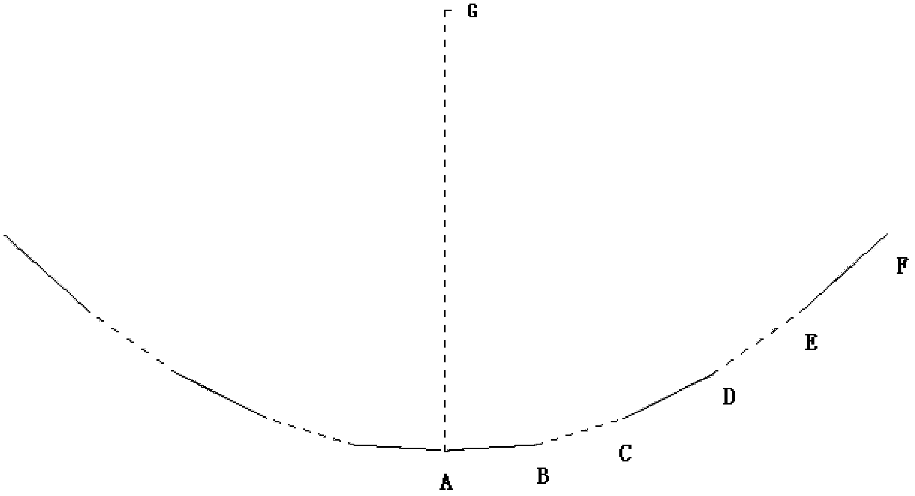
[0013] Let's explain with the help of attached drawings: figure 1 As a production example, the line segments AB, BC, CD, DE, EF are continuous line segments, AG is the symmetry axis of the parabola, and G is the focus. According to the parabolic equation x 2 =2py Set p=100mm, that is, focal length F=50mm, that is, AG=50mm

[0014] Then when x=10mm, y=0.5mm

[0015] When x=20mm, y=2.0mm

[0016] When x=30mm, y=4.5mm

[0017] When x=40mm, y=8.0mm

[0018] When x=50mm, y=12.5mm

[0019] When x=60mm, y=18.0mm

[0020] When x=70mm, y=24.5mm

[0021] When x=80mm, y=32.0mm

[0022] When x=90mm, y=40.5mm

[0023] When x=100mm, y=50.0mm

[0024] Take A(0,0), B(20,2), C(40,8), D(60,18), E(80,32) to make line segments AB, BC, CD, DE, EF, and make them Sequentially connected with the symmetrical line segment on the other side to form a continuous broken line, the continuous broken line extends along its plane to form a composite plane trough mirror. When the composite plane is ...


PUM

PropertyMeasurementUnit
Angleaaaaaaaaaa

Abstract

The application relates to a composite plane groove type condenser with high light condensation times and uniform condensation uniformity, which mainly solves the problem of the uneven condensation of a high-power groove type composite plane. The scheme of the condenser is as follows: the condenser comprises a flat surface reflector, a flat surface photic part, a mechanical supporting mechanism, and a one-dimension tracing and control part; the condenser is characterized in that fifty to N plane mirrors are bent or combined continuously according to a certain angle so as to form a groove type condenser system, wherein the included angle of the flat surface reflector and the flat surface photic part is between 0-45 degrees or 135-180 degrees, namely, the flat surface photic part is positioned on the upper part of the composite plane groove type condenser, the reflected light of multiple flat surface reflectors forms a 'surface focalization' on the flat surface photic part, the condensation times are greater than or equal to 50 times, and the composite plane groove type condenser can carry out one-dimension tracing similar to a groove type parabolic condenser. According to the method, the stable and uniform condensation of the plane mirror can be formed, the manufacture is simple and accurate, the material is saved, the cost is reduced, and the composite plane groove type condenser is beneficial to condensation photovoltaic power generation.

Description

technical field [0001] The invention relates to a composite planar groove type concentrator with high concentrating multiples and uniform concentrating light. Background technique [0002] With the development of solar photovoltaic industry, the concentrating industry is getting more and more development and attention. Existing light concentrating technologies such as the composite planar concentrator, application number: 2009100016672 The composite planar concentrator introduces a composite planar trough concentrator that can form uniform light concentration, which is beneficial to battery power generation, but the application reflects only The middle focal plane (Fig. 2) and the lower focal plane ( figure 1 ), the lower focusing surface method has a lower concentrating magnification in practical applications or even if a larger concentrating magnification is achieved, more concentrating mirror materials will be used correspondingly. It is too bulky to control the operati...

Claims


Application Information

Patent Timeline
IPC IPC(8): G02B19/00G02B7/182
Inventor 冯益安
Owner 冯益安
Learn More