Automatic neighboring relationship ability reporting method and user equipment
A technology of automatic neighbor relationship and user equipment, applied in wireless communication, electrical components and other directions, can solve the problems of waste of signaling configuration, high power consumption of UE, and failure of ANR configuration, and achieve the effect of avoiding waste.
- Summary
- Abstract
- Description
- Claims
- Application Information
AI Technical Summary
Problems solved by technology
Method used
Image

Examples
Embodiment 1
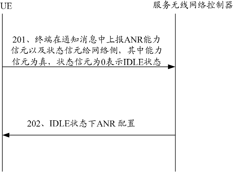
[0030] This embodiment describes the addition of two information elements to indicate support for ANR capability reporting in the IDLE state, figure 2 It is a schematic flow chart of the ANR capability reporting method described in Embodiment 1 of the present invention, as figure 2 As shown, the method includes the following steps:
[0031] Step 201: The UE reports the ANR capability and state information supporting the ANR capability as IDEL to the serving radio network controller in a notification message.
[0032] Wherein, the ANR capability is filled in the newly added ANR capability information element. If the ANR capability information element is true, there is a newly added state information element supporting the ANR capability, and the information element is filled with 0, indicating that the IDLE state is supported (other logical values can also be used to indicate the IDLE state).
[0033] Wherein, the notification message is an uplink control signaling messag...
Embodiment 3
[0044] This embodiment describes adding an information element to indicate support for ANR capability reporting in IDLE state, Figure 4 It is a schematic flow chart of the ANR capability reporting method described in Embodiment 3 of the present invention, as Figure 4 As shown, the method includes the following steps:
[0045] Step 401: The UE reports the ANR capability and state information supporting the ANR capability as IDEL to the serving radio network controller in a notification message.
[0046] Wherein, the ANR capability and its supported state are filled in the newly added ANR capability state information element. The information element is filled with 0, indicating that the ANR capability of the IDLE state is supported.
[0047] Wherein, the notification message is an uplink control signaling message such as a radio connection request message, a cell update message, or an uplink direct transmission message.
[0048] Step 402: The serving radio network controlle...
Embodiment 4
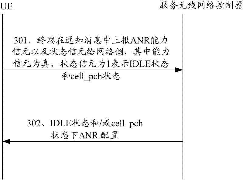
[0051] This embodiment describes adding an information element to indicate support for IDLE status and ANR capability reporting of cell_PCH, Figure 5 It is a schematic flow chart of the ANR capability reporting method described in Embodiment 4 of the present invention, as Figure 5 As shown, the method includes the following steps:
[0052] Step 501: The UE reports the ANR capability and state information supporting the ANR capability as IDEL and cell_pch to the serving radio network controller in a notification message.
[0053] Wherein, the ANR capability and its supported state are filled in the newly added ANR capability state information element. The cell is filled with 1, indicating that it supports the IDLE state and the ANR capability of cell_pch.
[0054] Wherein, the notification message is an uplink control signaling message such as a radio connection request message, a cell update message, or an uplink direct transmission message.
[0055] Step 502: The serving...
PUM
 Abstract
Description
Claims
Application Information
 - R&D
- Intellectual Property
- Life Sciences
- Materials
- Tech Scout
- Unparalleled Data Quality
- Higher Quality Content
- 60% Fewer Hallucinations
Browse by: Latest US Patents, China's latest patents, Technical Efficacy Thesaurus, Application Domain, Technology Topic, Popular Technical Reports.
© 2025 PatSnap. All rights reserved.Legal|Privacy policy|Modern Slavery Act Transparency Statement|Sitemap|About US| Contact US: help@patsnap.com