
Electromagnetic actuating device

A technology for adjusting equipment and electromagnetism, which can be used in electromagnets, mechanical equipment, electromagnets with armatures, etc., and can solve problems such as expensive adaptation of control facilities

Inactive Publication Date: 2014-12-17
SCHAEFFLER TECH AG & CO KG
View PDF10 Cites 0 Cited by
  • Summary
  • Abstract
  • Description
  • Claims
  • Application Information

AI Technical Summary

Problems solved by technology

In the case of motor control systems, however, such circuits are generally not provided and require costly adaptations of the control system
[0007] The same problem applies to the reversible energized adjustment device with magnetic coil known from WO 2009 / 018919 A1

Method used


Image

  • Electromagnetic actuating device

Examples


Embodiment Construction

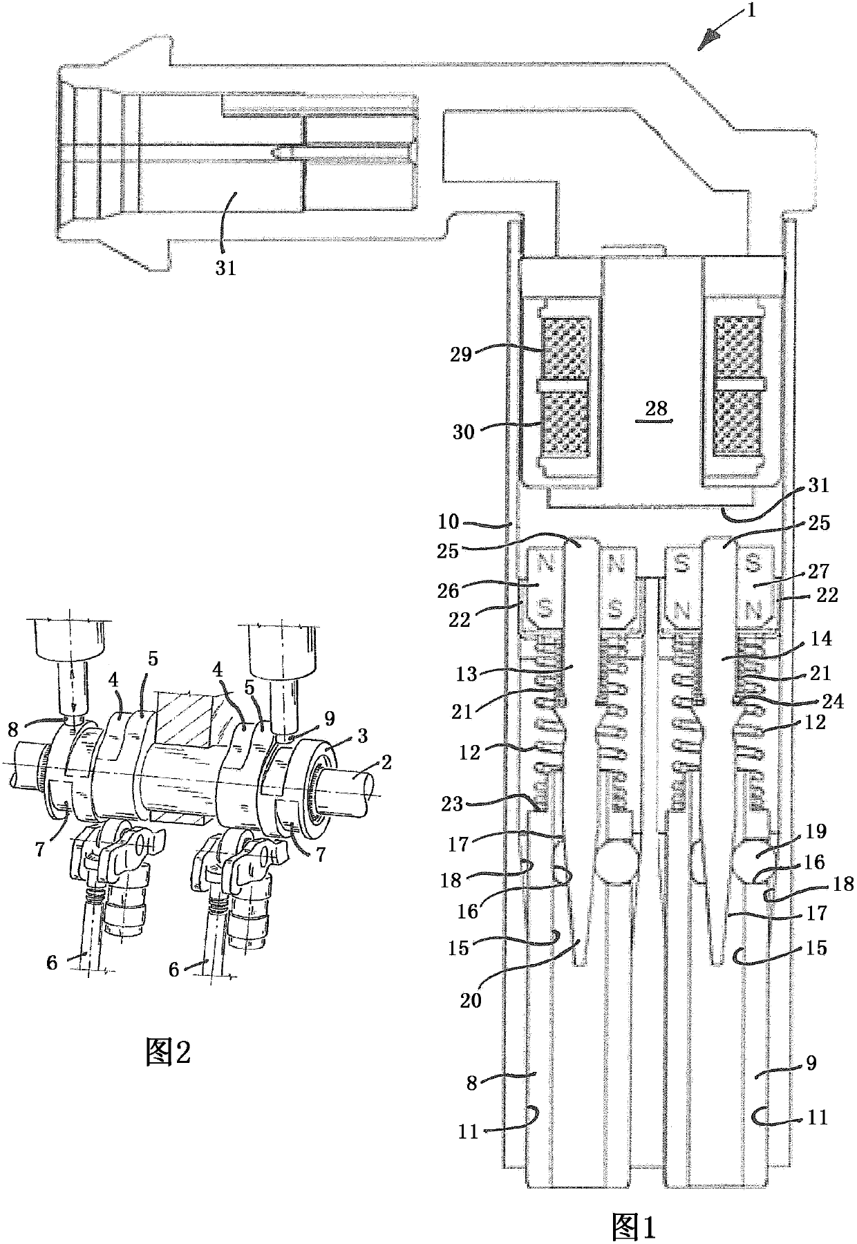
[0027] figure 1 An exemplary embodiment of an adjusting device 1 according to the invention is disclosed for actuating a basically known variable-stroke valve train of an internal combustion engine. The basic working principle of such a valve actuator is in figure 2It is shown in , and can be concluded that instead of a conventionally rigidly constructed camshaft, a carrier shaft 2 with a cam block 3 arranged thereon in a rotationally fixed and longitudinally displaceable manner is provided. The cam block 3 has two sets of axially adjacent cams 4 and 5 with different opening distributions, which are used for the operating point-dependent actuation of the gas exchange valve 6 . The movement of the cam piece 3 on the carrier shaft 2 required for the selective activation of the respective cam 4 or 5 takes place via helical movement grooves 7 on the cam piece 3 , which correspond to the direction of movement at Their orientation differs and each actuating pin 8 or 9 can be coup...


PUM


Abstract

An electromagnetic actuating device (1), having a housing (10), two actuating pins (8, 9), which are mounted in the housing so as to be movable independently of each other between a retracted non-working position and an extended working position, and an electrically energizable magnetic coil device for actuating the actuating pins and two permanent magnets (26, 27) which interact with the actuating pins with respect to the actuation. The permanent magnets are oriented so as to have opposite polarizations in the movement direction and are together associated with a stationary core region (28) of the magnetic coil device. The magnetic coil device is designed to generate a magnetic field, the direction of action of which reverses, dependent on the energizing of said magnetic coil device, wherein the magnetic field attracts the first permanent magnet and repels the second permanent magnet and vice versa. This is achieved in that the magnetic coil device should have two magnetic coils (29, 30) that are energizable independently of each other such that the magnetic field is generated with a first direction of action when the first magnetic coil is energized, and the magnetic field is generated with a second, reversed direction of action when the second magnetic coil is energized.

Description

technical field [0001] The invention relates to an electromagnetic adjustment device, comprising a housing, two actuators supported in the housing in a manner that can move independently of each other between a rest position retracted in the housing and a working position protruding from the housing. A movable pin, an electrically energizable magnetic coil arrangement for actuating the actuating pin and two permanent magnets cooperating with the actuating pin in the actuating sense, the two permanent magnets are magnetized in two poles and polarized opposite to each other in the direction of movement Orientation and collectively assigned to the static core region of the magnetic coil arrangement. In this case, the magnetic coil arrangement, depending on its current flow, generates a magnetic field in the core region which is reversed in direction of action, which attracts the first permanent magnet and pushes away the second permanent magnet and vice versa. Background techni...

Claims


Application Information

Patent Timeline
Patent Type & Authority Patents(China)
IPC IPC(8): H01F7/16F01L13/00
CPCH01F7/1646F01L13/0036H01F7/124
Inventor 哈拉尔德·埃伦特安德烈亚斯·内德尔
Owner SCHAEFFLER TECH AG & CO KG
Learn More