

Sampling tool for selective laser melting equipment
A technology of selective laser melting and equipment, which is applied in the direction of additive processing, etc., can solve problems such as hidden dangers of the substrate, and achieve the effects of safe use, stable movement, and small force requirements
- Summary
- Abstract
- Description
- Claims
- Application Information
AI Technical Summary
Problems solved by technology
Method used
Image

Examples
Embodiment 1
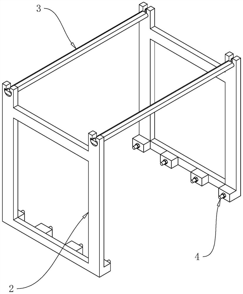
[0049] refer to Figure 4 , the side bracket 2 includes an upper cross bar 21, a lower cross bar 22 and a longitudinal bar 23, the upper cross bar 21 and the lower cross bar 22 are arranged parallel to each other, and the upper cross bar 21 and the lower cross bar 22 are arranged in an up-and-down positional relationship, and the longitudinal bar 23 is provided with at least one, and the upper and lower ends of each longitudinal bar 23 are respectively connected with the upper cross bar 21 and the lower cross bar 22; There are several pieces of projections 24 , and each piece of connecting piece 4 is respectively arranged on the side of each piece of projections 24 away from the side bracket 2 .
[0050] refer to Figure 5 , the upper end of each side bracket 2 is provided with a first engaging groove 5, the first engaging groove 5 is arranged on the side of the side bracket 2 away from the protrusion 24, and the upper end of each side bracket 2 is also provided with There i...
Embodiment 2
[0058] refer to Figure 8 and Figure 9 The difference between this embodiment and Embodiment 1 is that the opposite sides of the two side brackets 2 are provided with second engagement grooves 6, and the opposite sides of the two side brackets 2 are provided with second slots. The installation groove 61; wherein, the second clamping groove 6 communicates with the second installation groove 61, the width of the second installation groove 61 is slightly larger than the thickness of the connecting rod 3, the width of the second installation groove 61 is smaller than the width of the connecting rod 3, and The depth of the second installation groove 61 is slightly greater than the width of the connecting rod 3, the width of the second engaging groove 6 is slightly greater than the width of the engaging groove, and the end of the connecting rod 3 is provided with a second annular groove 32, the second annular groove The width of 32 is set to be the same as the distance between the...
Embodiment 3
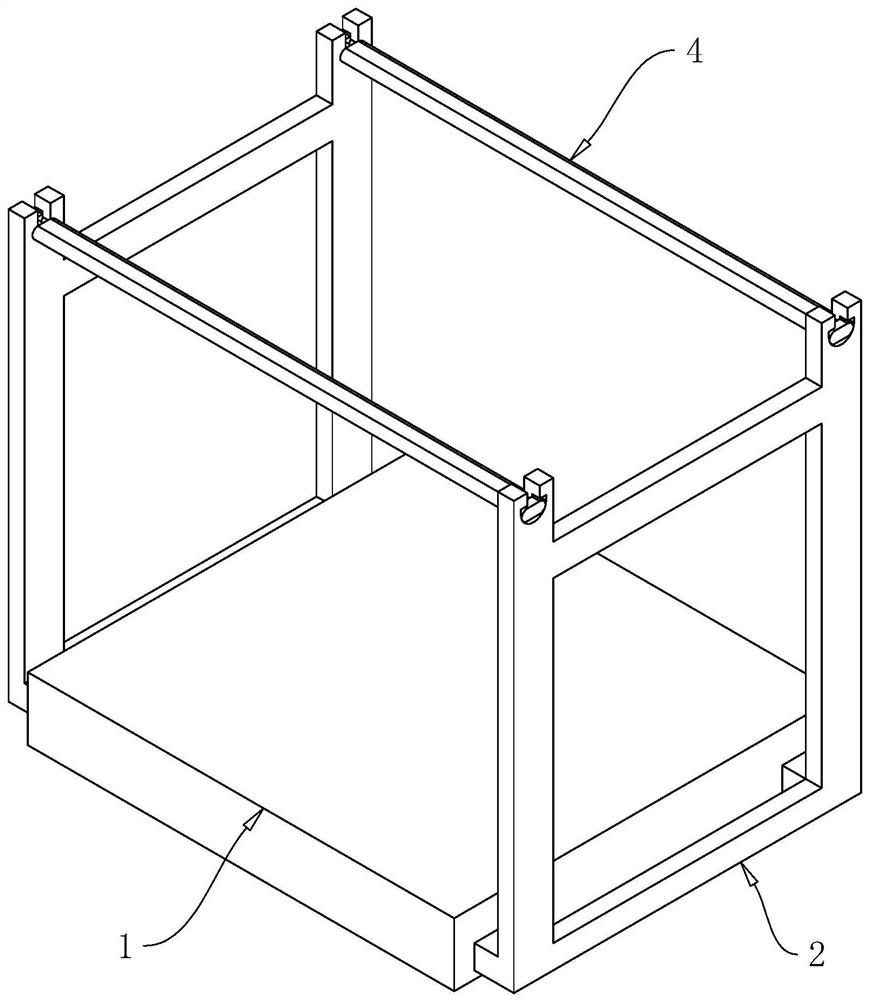
[0062] refer to Figure 10 and Figure 11 The difference between this embodiment and Embodiment 1 is that each upper cross bar 21 is provided with a first limiting groove 211, the lower end of the first limiting groove 211 communicates with the lower side of the upper cross bar 21, and The width of the first limiting groove 211 is the same as the thickness of the upper cross bar 21, and the end of the connecting rod 3 is provided with a second limiting groove 33, and the upper end of the second limiting groove 33 communicates with the upper side of the connecting rod 3 , and the width of the second limiting groove 33 is set to be the same as the thickness of the upper cross bar 21; wherein, when the first limiting groove 211 and the second limiting groove 33 can engage with each other.
[0063] The implementation principle of embodiment 3 is:
[0064] When it is necessary to fix the connecting rod 3 and the side bracket 2 as a whole, it is only necessary to place the two end...
PUM
 Abstract
Description
Claims
Application Information