Driving mechanism of material feeding manipulator

A driving mechanism and manipulator technology, applied in the direction of conveyor objects, transportation and packaging, etc., can solve the problems of unreliable insertion, high labor intensity, high labor cost, etc., and achieve stable and reliable wick insertion, high degree of automation, and improved The effect of processing efficiency

Inactive Publication Date: 2014-04-02
DEQING MINGYU LIGHTING
View PDF7 Cites 0 Cited by
  • Summary
  • Abstract
  • Description
  • Claims
  • Application Information

AI Technical Summary

Problems solved by technology

[0002] The bulb sealing production line is used to complete the bulb sealing, exhaust and inflation processing. The existing production line needs to manually insert the wick into the sealing fixture on the turntable of the sealing equipment, which has low processing efficiency, high labor cost, high labor intensity, and The installation is not firm and reliable, etc.

Method used


Image

  • Driving mechanism of material feeding manipulator
  • Driving mechanism of material feeding manipulator
  • Driving mechanism of material feeding manipulator

Examples


Embodiment 1

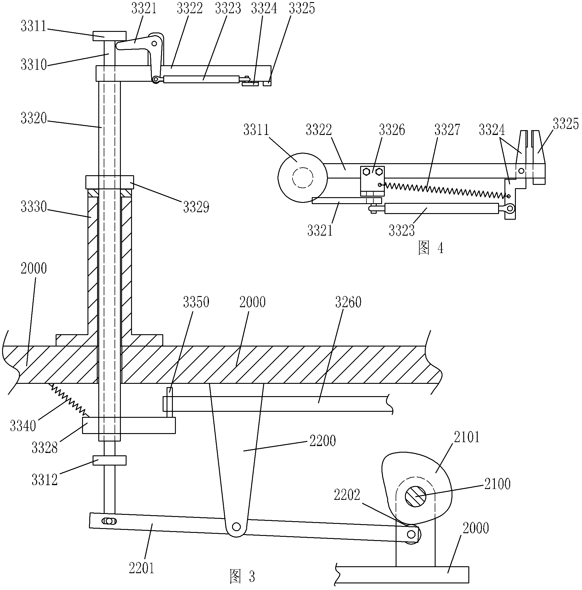
[0017] Such as image 3 , Figure 5 The driving mechanism of a feeding manipulator shown includes a rotating driving structure of the sleeve rod 3320 and a lifting and lowering driving structure of the sleeve rod 3320 and the core rod 3310 . The rotation driving structure of the sleeve rod 3320 includes a swinging member 3328 fixed on the lower end of the sleeve rod 3320. One swinging end of the swinging member 3328 is fixed with a driving rod B3350 that matches the upper tooth groove 3261 of the toggle toothed disc 3260. The swinging member The other swing end of 3328 is connected with frame 2000 through extension spring 3340 . The lifting and lowering drive structure of the sleeve rod 3320 and the core rod 3310 includes a limit block 3312 fixed on the lower end of the core rod 3310 and capable of contacting the bottom of the sleeve rod 3320 to limit the position. The lower end of the core rod 3310 is movably connected with one end of the lever 2201. The other end of the le...


PUM


Abstract

The invention discloses a driving mechanism of a material feeding manipulator. The driving mechanism of the material feeding manipulator comprises a core rod and a sleeve rod sleeved out of the core rod, wherein the sleeve rod is vertically inserted on a rack table board through a bearing base; a spacing block capable of butting against and bearing the bearing base is fixed above the bearing base for the sleeve rod, thus the sleeve rod is restricted from falling; the sleeve rod is connected with a sleeve rod rotating and driving structure which drives the sleeve rod to rotate; and the core rod is connected with a core rod and sleeve rod lifting driving mechanism which drives the core rod to lift with the sleeve rod. The technical scheme has the advantages of simple and reasonable structure, stable and reliable motions, high automation degree, low manufacturing cost and the like.

Description

technical field [0001] The invention belongs to the field of bulb manufacturing, and in particular relates to a driving mechanism for a feeding manipulator used in a bulb sealing and arranging production line. Background technique [0002] The bulb sealing production line is used to complete the bulb sealing, exhaust and inflation processing. The existing production line needs to manually insert the wick into the sealing fixture on the turntable of the sealing equipment, which has low processing efficiency, high labor cost, high labor intensity, and insertion The installation is not firm and reliable and other problems. For this reason, the inventor designed a feeding device for the bulb sealing production line. By placing the wick on the turntable in advance, the manipulator picks it up and inserts it into the sealing fixture on the turntable of the sealing equipment, which reduces labor and labor intensity. , Improve the processing efficiency of the production line, and t...

Claims


Application Information

Patent Timeline
Patent Type & Authority Patents(China)
IPC IPC(8): B65G47/74
Inventor 陆建明
Owner DEQING MINGYU LIGHTING
Why Eureka
Try Eureka