
Sealing system for reciprocating piston rod of reciprocating compressor

A sealing system and reciprocating operation technology, which is applied to the sealing of engines, components of pumping devices for elastic fluids, and variable-capacity liquid machinery, etc. question

Inactive Publication Date: 2012-08-22
HOERBIGER KOMPRESSORTECHNIK HLDG GMBH
View PDF8 Cites 8 Cited by
  • Summary
  • Abstract
  • Description
  • Claims
  • Application Information

AI Technical Summary

Problems solved by technology

If the hydraulic supply blocked by the sealing medium is interrupted, the sealing function of the sealing system is no longer there, and the compressed medium may enter the crankcase from the cylinder and from the crankcase into the surrounding environment, which will also cause the compressor to be forced to stop
Due to the above problems, the hydraulic supply cannot be simply cut off in the event of a fault, so the entire compressor must be stopped for maintenance and troubleshooting in the event of a fault
This leads to production stoppages, which in practice can cause large economic losses
[0004] A further problem of WO 2010 / 079227 A1 is that in order to reliably recover the sealing medium, a complex and tedious design of the various sealing elements and of the high-pressure and discharge lines is required, as shown for example in FIG. 6 of WO 2010 / 079227 A1
This makes such an arrangement and above all the retrofitting of existing compressors very complex and therefore economically uneconomical

Method used


Image

  • Sealing system for reciprocating piston rod of reciprocating compressor
  • Sealing system for reciprocating piston rod of reciprocating compressor
  • Sealing system for reciprocating piston rod of reciprocating compressor

Examples


Embodiment Construction

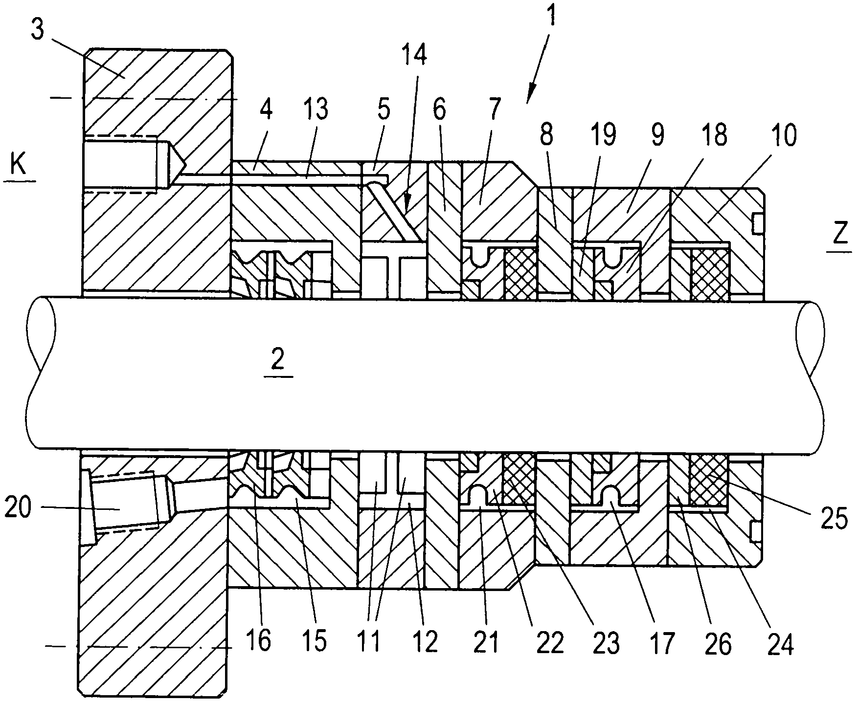
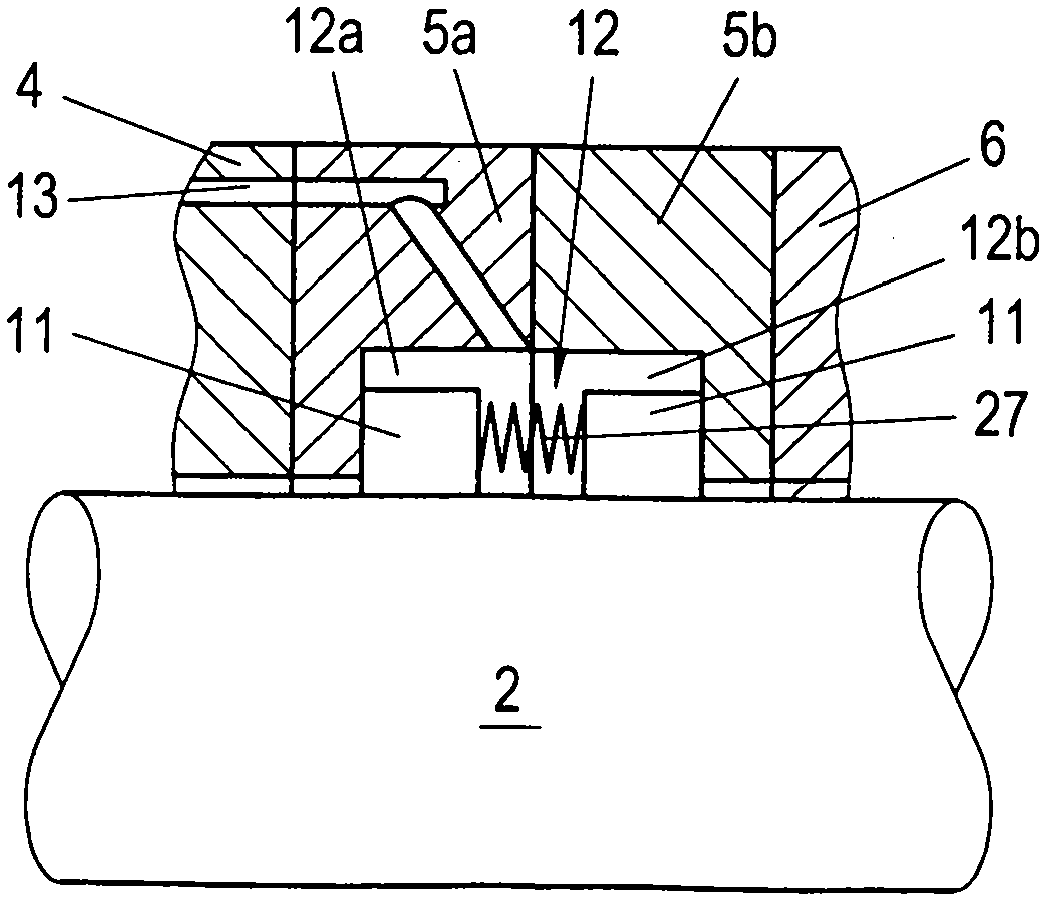
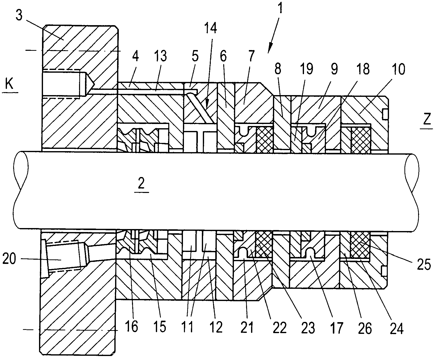
[0015] according to figure 1 A kind of favorable design shown, the hermetic seal that the present invention proposes comprises a kind of sealing system 1, and it is equipped with several chamber discs 3,4,5,7,9,10, and in a part these chambers A plurality of sealing elements with different functions are arranged in the chamber disc. The chamber disks 3 , 4 , 5 , 7 , 9 , 10 can be connected to one another in a known manner by means of through-going pins. The sealing system 1 can be embedded in the (not shown) housing of the compressor in a manner known for a long time, wherein the first chamber disk 3 is designed as a flange, by means of which the sealing The system 1 is fixed in the housing, for example by means of screws distributed over the circumference. The sealing system 1 provides a seal between a chamber Z on the cylinder side with high pressure and a chamber K on the crankcase side with generally atmospheric pressure. "Sealing" here means preventing the occurrence o...


PUM


Abstract

The invention provides a gas-proof sealing system, which can retain the functions in an at least enough way even if one component (e.g. hydraulic supplying or sealing element) is faulty and prevent a compressor from being down. A scraper recess (15) is equipped on the sealing system (1) end located on a crankcase side. A gas-proof scraping ring (16) is equipped inside the scraper recess. A sealing ring recess (17) is equipped on the sealing system (1) end (Z) located on the cylinder side. A sealing ring device (18) is equipped inside the sealing ring recess. A barrier recess (14) is located axially between the scraper recess (15) and the sealing ring recess (17). A discharge pipeline (20) is equipped inside the sealing system (1). The discharge pipeline is communicated with the space between the barrier recess (14) and the scraper recess (15).

Description

technical field [0001] The invention relates to an airtight sealing system for a reciprocating piston rod of a piston compressor, wherein a first sealing element and a second sealing element are arranged in the sealing system, the two sealing elements are arranged in the sealing system In the blocking cavity, and set the input pipeline for the sealing medium leading into the blocking cavity. Background technique [0002] In certain uses of compressors, such as on compression stations for transporting natural gas, it has become more and more important to minimize the leakage of the compressed medium (such as natural gas) from the compressor for reasons of environmental protection ( Also due to increasingly stringent regulations). This leakage essentially occurs along the reciprocating piston rod, which is usually sealed relative to the compressor housing by means of so-called long-known sealing systems. The high requirements for tightness must therefore be met by convention...

Claims


Application Information

Patent Timeline
IPC IPC(8): F16J15/40F16J15/56F16J15/3256
CPCF04B39/0094F04B39/041F04B39/042F04B53/143F16J15/004F16J15/006F16J15/008F16J15/28F16J15/40F16J15/56
Inventor T·林德纳-西尔弗斯特C·霍尔德C·科恩比切勒A·布兰德尔
Owner HOERBIGER KOMPRESSORTECHNIK HLDG GMBH
Learn More