Electromagnetic electric control valve

An electric control valve and electromagnetic technology, which is applied in valve details, valve devices, engine components, etc., can solve problems such as uneven thermal expansion and contraction of the valve body and valve core, affecting stability and reliability, and coil burnout. Reach the effect of reducing power-on running time, short power-on running time, and improving operation stability

Inactive Publication Date: 2013-07-17
北京天易传动科技股份有限公司
View PDF5 Cites 0 Cited by
  • Summary
  • Abstract
  • Description
  • Claims
  • Application Information

AI Technical Summary

Problems solved by technology

The disadvantage of the existing solenoid valve is that when the valve core needs to maintain the working condition after displacement, the electromagnet is always in the energized state, which requires energy consumption, especially when the valve core needs to maintain the displacement for a long time or for a long time. In this case, the energy consumption is large, and because the current passes through the coil to form an eddy current, the temperature rises quickly, and the coil is easy to be burned. There is also heat generated by the coil being energized for a long time, which will conduct heat energy to the valve body, causing the valve body and the valve core to generate heat. Uneven thermal expansion and cold contraction are prone to cause the valve core to be stuck and cause failure, affecting the stability and reliability of operation

Method used


Image

  • Electromagnetic electric control valve
  • Electromagnetic electric control valve
  • Electromagnetic electric control valve

Examples


Embodiment Construction

[0048] See attached image.

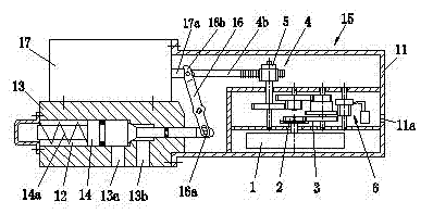
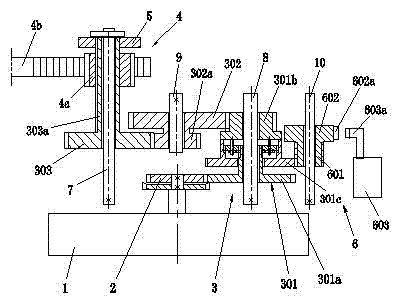
[0049] The present invention includes: a valve body 13 having a valve cavity 12, the valve body 13 has an inlet 13a and an outlet 13b, the inlet 13a and the outlet 13b are respectively communicated with the valve cavity 12, and the valve cavity 12 has a valve core 14;

[0050] The electromagnet 17 for driving the valve core 14 to move;

[0051] The return spring member 14a acting on the valve core 14; the valve core 14 and its return spring member 14a have various structural forms. figure 1 and Figure 11 As shown in the figure, the valve core 14 is a cylindrical structure, which cooperates with the circular valve cavity 12. The middle section of the valve core 14 is the working section that shuts off or connects to the inlet 13a, and the valve stem at the left end is provided with a return spring for resetting the valve core 14. Part 14a, the valve stem of the right section extends out of the valve body, and the figure is a normally closed valve...


PUM


Abstract

An electromagnetic electric control valve comprises a valve body (13) with a valve cavity (12), an electromagnet (17) for driving a valve core (14) to move, a return spring member (14a) acting on the valve core (14), a lever member (16) which can swing around a supporting point of the lever member (14) and is used for pushing the valve core (14) to move and an electric control device (15) for keeping working states of the valve core (14) after displacement. An inlet (13a) and an outlet (13b) on the valve body (13) are respectively communicated with the valve cavity (12), and the valve core (14) is arranged in the valve cavity (12). One end (16a) of the lever member (16) is connected with the extending end of a valve rod of the valve core (14), and the electromagnet (17) is provided with amoving iron core push rod (17a) capable of pushing the other end (16b) of the lever member (16). A connecting member (4b) of a retention mechanism (4) in the electric control device (15) is connectedwith the end (16b) of the lever member (16). The electromagnetic electric control valve has the advantages of being energy-saving, stable and reliable in operation and the like.

Description

technical field [0001] The invention relates to the improvement of the valve, in particular to an electromagnetic electric control valve which uses an electromagnet to push the valve core to displace, and uses a motor to drive a transmission mechanism to maintain the working condition after the valve core is displaced. Background technique [0002] Solenoid valves are widely used in different workplaces. The existing solenoid valve includes a valve body, the valve body has a valve cavity, the valve body has an inlet and an outlet, the inlet and outlet are respectively connected with the valve cavity, and a valve core is arranged in the valve cavity; it also includes a valve for pushing the valve. The electromagnetic device for core movement, the electromagnetic device includes a coil, a static iron core, a moving iron core and a spring for restoring the moving iron core. The moving iron core is similar to a push rod and is used to push the valve core to move. There are two ...

Claims


Application Information

Patent Timeline
Patent Type & Authority Patents(China)
IPC IPC(8): F16K31/06F16K31/04F16K31/53
Inventor 薛玉林罗峪宏汤卓
Owner 北京天易传动科技股份有限公司
Why Eureka
Try Eureka