
Method for reducing output voltage ripples of Boost power electronics inverter

An output voltage ripple, power electronics technology, applied in the field of power electronic converter switching control, can solve the problem of large output voltage ripple, and achieve the effect of reducing output voltage ripple and speeding up output voltage response speed

Inactive Publication Date: 2012-08-22
XIAN UNIV OF TECH
View PDF3 Cites 7 Cited by
  • Summary
  • Abstract
  • Description
  • Claims
  • Application Information

AI Technical Summary

Problems solved by technology

[0003] The present invention provides a method for reducing the output voltage ripple of Boost power electronic converter switching control by using the feedback idea, so as to overcome the shortcomings of the existing control method to control the output voltage ripple

Method used


Image

  • Method for reducing output voltage ripples of Boost power electronics inverter
  • Method for reducing output voltage ripples of Boost power electronics inverter
  • Method for reducing output voltage ripples of Boost power electronics inverter

Examples


Embodiment Construction

[0026] 1) Description of the controlled object

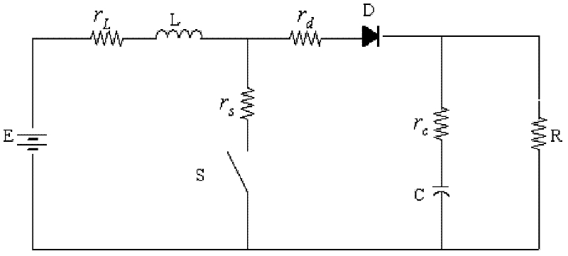
[0027] Boost converter circuit such as figure 1 As shown, the circuit is composed of an input power supply E, an inductor L, a diode D, a switch S, a capacitor C and a load R, where the inductor L and the equivalent first resistance r L In series, the diode D and the equivalent second resistor r d In series, the switch S and the equivalent third resistance r s In series, capacitor C and equivalent fourth resistor r c in series. According to the basic law of the circuit, the dynamic equation of the Boost converter can be obtained

[0028] X · = A k X + B k U - - - ( 1 )

[0029] where X=[x 1 x 2 ] T =[i L v C ] T , T represents vector transposition, i L is the inductor current value, v C ...


PUM


Abstract

The invention provides a method for reducing output voltage ripples of a Boost power electronics inverter. The method comprises the following steps of: firstly calculating a current reference value Iref and then calculating a voltage reference value Vref; then calculating a minimal load resistance value Rmin and determining a ripple voltage Vripple; and finally on the premise that the load resistance of the convertor is greater than the Rmin, controlling a switch of the convertor as follows: measuring an output voltage vC, measuring an inductive current iL, and when the vC is less than the reference voltage Vref and the iL is less than or equal to zero, controlling the switch to be switched on; and measuring the inductive current iL, and when the iL is greater than the reference current Iref, controlling the switch to be switched off. The method provided by the invention has the beneficial effects of quickening the output voltage response speed of the convertor and reducing the output voltage ripples of the convertor.

Description

technical field [0001] The invention belongs to the field of electric energy conversion devices, and relates to a switching control method of a power electronic converter, which is used for reducing the output voltage ripple of the power electronic converter under switching control. Background technique [0002] Electric energy is the most important form of energy in modern society, and the power electronic converter realizes the conversion of electric energy and is the key device for the effective utilization of electric energy. A power electronic converter is a typical hybrid system with both discrete events of switching devices being turned on and off, and state variables that change continuously when the switch is in a specific state. A hybrid system is a unified dynamic system formed by the interaction of a continuous variable system and a discrete event dynamic system. It is possible for the circuit to be linear in each switching state, but the switching of the switch...

Claims


Application Information

Patent Timeline
Patent Type & Authority Applications(China)
IPC IPC(8): H02M1/14
Inventor 李洁郑婷任海鹏
Owner XIAN UNIV OF TECH
Learn More