A method of monitoring a spray dryer and a spray dryer comprising one or more infrared cameras

An infrared camera, spray dryer technology, applied in drying solid materials, drying safety systems, heating to dry solid materials, etc., can solve problems such as high cost

Active Publication Date: 2012-08-22
GEA PROCESS ENG
View PDF4 Cites 8 Cited by
  • Summary
  • Abstract
  • Description
  • Claims
  • Application Information

AI Technical Summary

Problems solved by technology

[0007] The alternative of applying an automatic image analysis system is also disadvantageous, since this needs to be adapted to each specific spray dryer, and due to the considerable cost of the software

Method used


Image

  • A method of monitoring a spray dryer and a spray dryer comprising one or more infrared cameras
  • A method of monitoring a spray dryer and a spray dryer comprising one or more infrared cameras
  • A method of monitoring a spray dryer and a spray dryer comprising one or more infrared cameras

Examples


Embodiment Construction

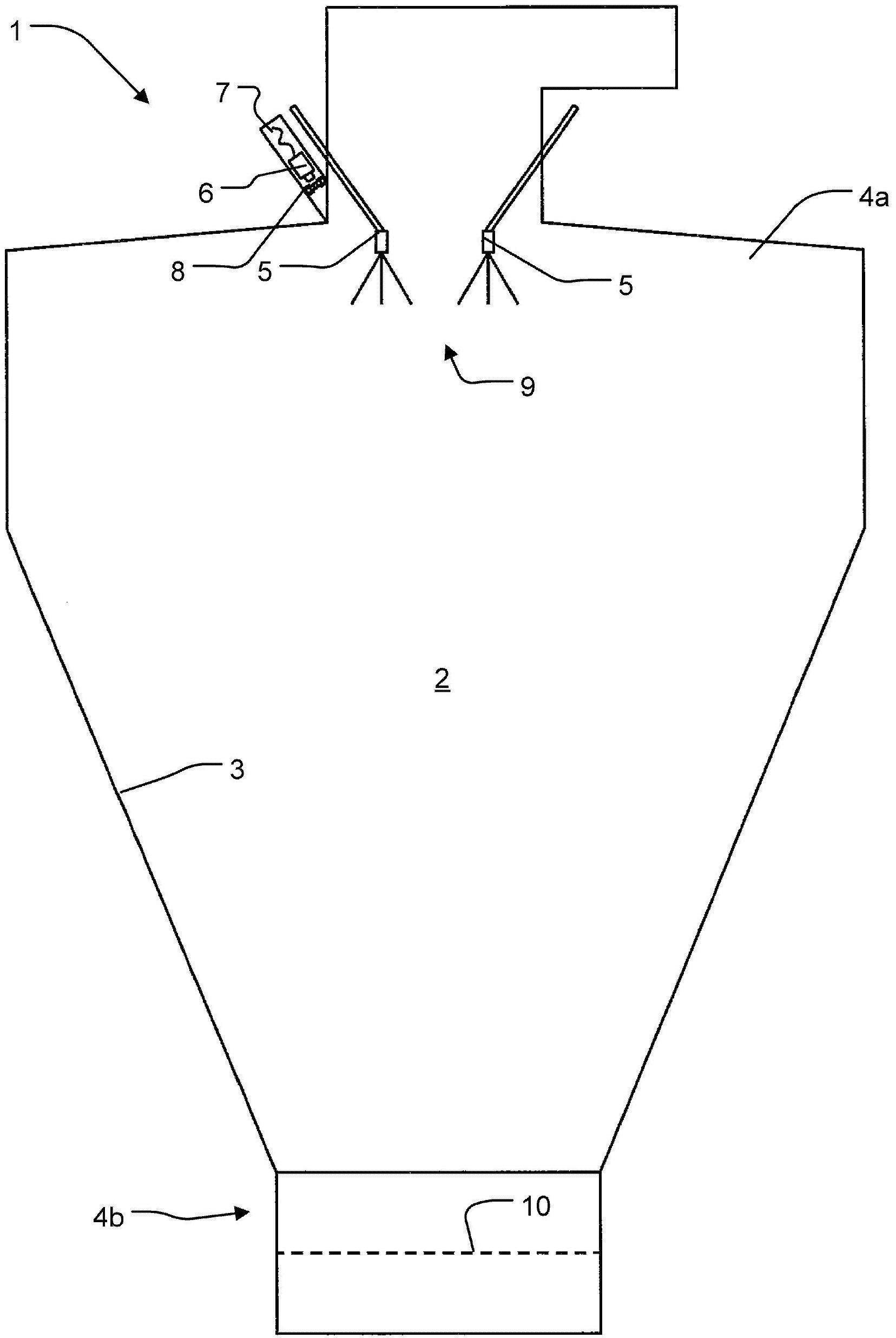
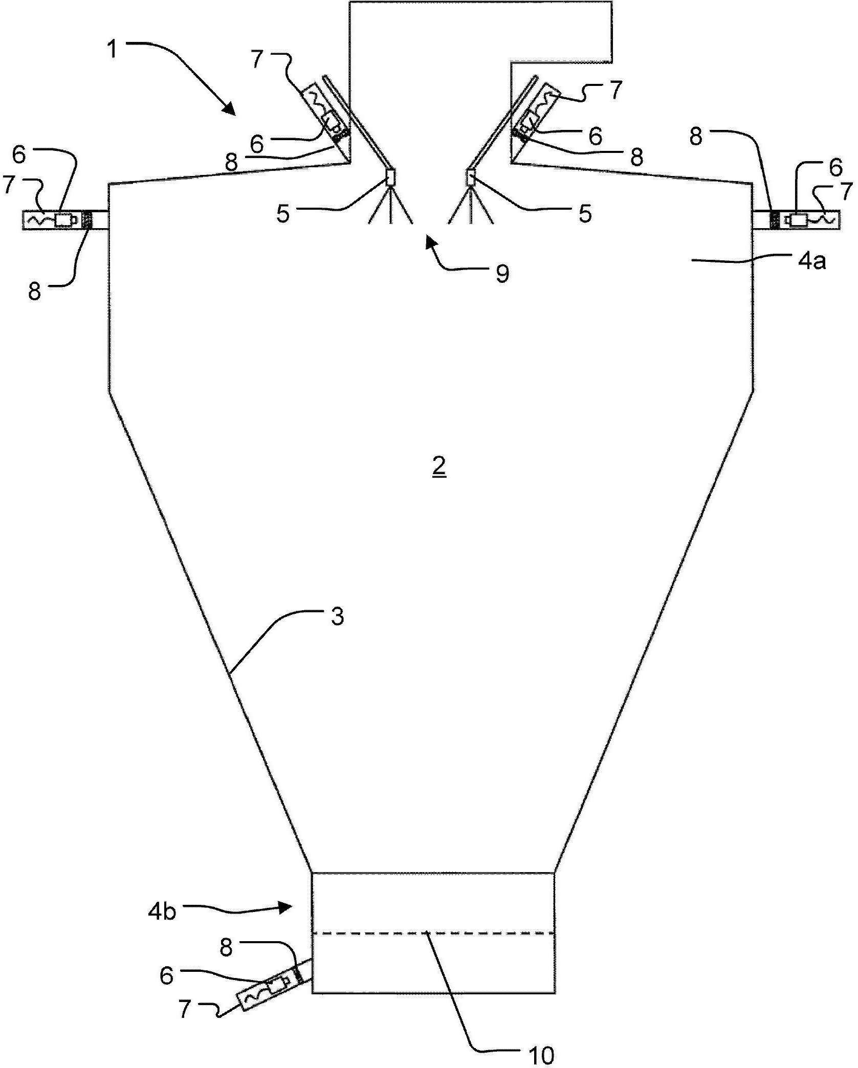
[0031] figure 1 An example of a spray dryer 1 with a spray drying chamber 2 is shown, which includes a substantially cylindrical top portion 4a, a conical wall 3, and a narrow lower portion 4b. An atomizing device 9 is provided in the top 4a. An air diffuser connected to the air inlet, which may be a straight air inlet, a radial inlet, or a tangential inlet, is provided in the top of the spray drying chamber (not shown). The air diffuser may, for example, have the form described in the applicant's co-pending international application No. WO2007 / 071238 or PCT / DK2009 / 050277, or may be similarly designed as other conventional air diffusers.

[0032] The spray dryer 1 comprises a supply device to the atomization device 9 in a manner known per se. The air diffuser may be installed above or in the ceiling of the drying chamber 2 of the spray dryer 1, or installed in the top 4a of the drying chamber 2, for example. Depending on the size of the drying chamber 2, there may be more than ...


PUM


Abstract

The spray dryer (1) comprises a spray drying chamber(2)having a substantially cylindrical top section (4a), a conical wall (3)and a narrowed lower section (4b). In the top section (4a), atomizing means (9)is provided. One or more cameras (6) are associated with the drying chamber (2) in order to monitor the process. At least one of the cameras is an infrared camera adapted for measuring the temperature within a predefined area.

Description

Technical field [0001] The present invention relates to a method for monitoring a spray dryer, which includes the steps of: setting a spray drying chamber; and associating one or more cameras with the spray drying chamber, the one or more cameras having a view inside the spray drying chamber field. In addition, the present invention relates to a spray dryer including a spray drying chamber, an atomizing device, and one or more cameras positioned to be associated with the spray drying chamber. Background technique [0002] The spray drying method is a well-known method for turning liquid products into powder products. The drying method takes place in a drying chamber where the dry air is combined with a supply (ie, atomized into droplets) provided by one or more nozzles or other shaped parts of an atomizer (such as a rotary atomizer) Liquid) contact. Dry air enters the drying chamber through an air diffuser positioned at or near the top of the drying chamber. Another drying de...

Claims


Application Information

Patent Timeline
Patent Type & Authority Applications(China)
IPC IPC(8): B01J2/04B01J2/16F26B3/12G01N21/85
CPCB01J2/04B01J2/16B05B12/082F26B3/12F26B25/009G01N21/85G01N2021/8564
Inventor 托马斯·威勒姆·延森约翰尼·邦克
Owner GEA PROCESS ENG
Why Eureka
Try Eureka