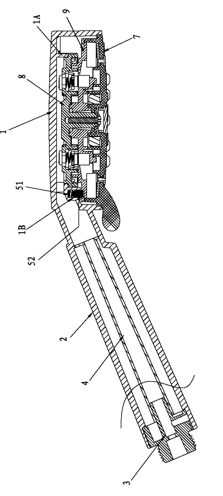
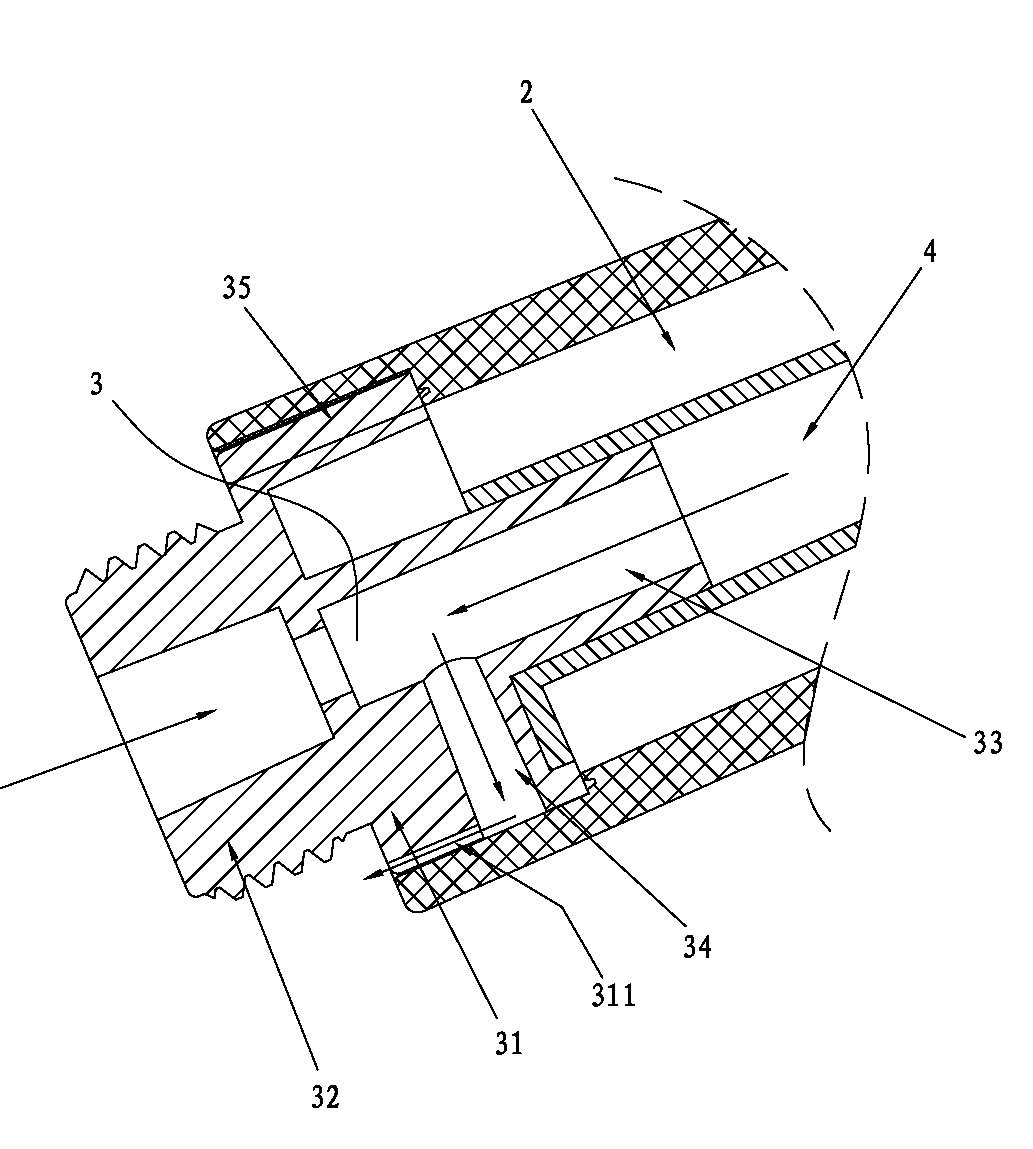
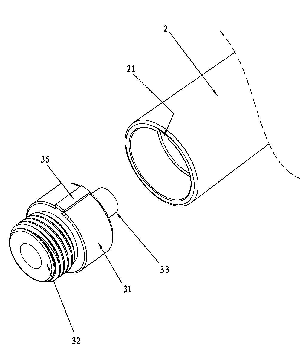
[0032] The present invention will be further described below in conjunction with the drawings.
[0033] Such as figure 1 , figure 2 , image 3 As shown, an air-injected pressurized hand shower includes a housing 1, a hollow handle 2, a venturi tube 3, and a water outlet assembly arranged in the lower opening of the housing. The housing 1 and the handle 2 are integrally formed , The venturi tube 3 is arranged at the end of the handle 2; one end of the venturi tube 3 is in communication with the water source, and the other end is in communication with the cavity between the top plate of the housing 1 and the water outlet assembly; the venturi tube 3 includes a body 31, The water inlet port 32 and the water outlet port 33 are provided with a radial air inlet 34 on the main body 31 and an axial positioning rib 35 on the outer circumferential surface; a positioning groove 21 is provided on the inner wall of the open end of the handle 2 , The positioning rib 35 is matched with the positioning groove 21; the body 31 has an axial air guide groove 311, and the air guide groove 311 extends from the water inlet port 311 of the body 31 to the air inlet 34 and is connected to the air inlet 34 Communicate
[0034] The air guide groove 311 and the inner wall of the open end of the handle 2 constitute an air guide water channel.
[0035] It also includes a water pipe 4, one end of the water pipe 4 is connected with the outlet port 33 of the venturi tube 3, and the other end is connected with the cavity between the top plate of the housing 1 and the water outlet assembly.
[0036] The air guide water channel refers to the air entering the body, the water outlet port 33 and the water pipe 4 through the air guide water channel, the air inlet 34 when in use; when the use is stopped, the remaining space between the top plate of the housing 1 and the water outlet assembly The water in the cavity is discharged through the air guiding water channel through the water guiding pipe 4, the water outlet port 33, and the air inlet 34.
[0037] Such as Figure 4 , Figure 5 , Image 6 , Figure 7 As shown, the water outlet assembly includes a water diversion seat 8, a water diversion plate 9, a positioning device 5, an impeller 6 and a water outlet cover 7;
[0038] The center of the lower end surface of the water diversion seat 8 has a circular rod 81, and the radial edge has an interface 82. The water diversion seat also has a receiving cavity 83 with a lower opening on a diameter line. The top plate of the empty cavity 83 has Water inlet; there is also an outer ring platform 84 on the top of the water divider seat;
[0039] The center of the water diversion plate 9 is provided with a shaft sleeve 91, two sets of water guiding devices 92 on a diameter line surrounding the shaft sleeve 91, and a water diversion plate interface 93 surrounding the water guiding device; There is an annular groove 94 on the radial edge, and an inner water guiding groove 95 and a middle water guiding groove 96 on the lower end surface;
[0040] The upper end surface of the water outlet cover 7 has a water channel 71 in the cover, a water channel 72 in the cover and a water channel 73 outside the cover; the gap between the water channel 71 in the cover and the shaft seat 74 on the center of the water outlet cover 7 is formed Leaf cavity; the water guide groove 71 in the cover communicates with the leaf cavity; the water outlet surface of the leaf cavity is covered with massage water holes; the water outlet surface of the water guide groove 72 in the cover is covered with atomized water holes, and there is water flow in the water guide groove 73 outside the cover Hole; the water outlet cover 7 is inserted into the housing 1 and fixedly connected;
[0041] It also includes a spring 10 and two floating rubber cylinders 11. The floating rubber cylinder 11 has an upper opening and a water outlet hole on the bottom plate;
[0042] Such as figure 1 As shown, the housing 1 has a ring seat 1A, the top of the water diversion seat 8 is inserted into the ring seat 1A and fixedly connected, and the connecting pin 85 on the top of the water diversion seat 8 is inserted into the pin seat in the housing 1. The ring table 84 is matched with the ring seat 1A to stop, thereby fixing the water diversion seat 8 and the housing 1 together; the water diversion tray interface 93 is inserted into the interface 82 of the water diversion seat 8 to rotate and fit and be liquid sealed, the water diversion plate 9 The upper shaft sleeve 91 is matched with the counterbore surrounding the circular rod 81 and is liquid-sealed; the shaft seat 74 on the water outlet cover 7 is inserted into the shaft sleeve 91 of the water diversion tray 9, and the inner water guiding groove 95 and the middle water guiding groove 96 are respectively The upper end of the outer annular wall plate of the water guide groove 73 outside the cover is fitted with the annular groove 94 of the water distribution tray 9 and is liquid-sealed; the inner wall of the housing 1 and the outer cover The outer annular wall plate of the water guide groove 73 rotates and cooperates;
[0043] The impeller 6 is pivotally connected to the shaft seat 74 on the water outlet cover 7; the positioning device 5 is arranged on the housing 1, and the positioning device 5 is positioned in cooperation with the water diversion tray 9;
[0044] The floating glue cylinder 11 is arranged in the empty cavity 33, and the spring 10 is matched with the top plate of the empty cavity 83 and the bottom plate of the floating glue cylinder 11; the bottom plate of the floating glue cylinder 11 is matched with the water guiding device 92 on the water diversion plate 9 to guide The water device 92 is in communication with the inner water guiding groove 95, the middle water guiding groove 96, and the water diversion tray 9 outside the middle water guiding groove 96;
[0045] The circular rod 81 passes through the shaft sleeve 91 of the water diversion tray 9 and the shaft seat 74 on the water outlet cover 7 to be screwed with screws.
[0046] Such as Figure 4 , Figure 5 As shown, there is a pin plate 97 on the water diversion pan 9 and a pin plate insertion hole 75 on the water outlet cover 7. The pin plate 97 is inserted into the pin plate insertion hole 75 to prevent the water outlet cover 7 and the water diversion plate 9 from rotating relative to each other.
[0047] It also includes an atomizing device. The atomizing device includes an annular chassis 121, a water outlet 122 and spray particles 123. The upper opening of the water outlet 122 is in communication with the atomizing hole on the annular chassis 121, and the spray particles 123 are arranged in the annular Inside the atomization hole on the chassis 121;
[0048] The annular chassis 121 is embedded in the water guiding groove 72 in the cover, and the water outlet 122 extends from the atomized water hole;
[0049] The spray particles 123 are columnar with spiral water grooves on the outer surface.
[0050] It also includes a water spray device. The water spray device includes a circular base plate 131 and a water spray nozzle 132; the circular base plate 131 is embedded in the water guide groove 73 outside the cover, and the water spray nozzle 132 extends from the water flow hole.
[0051] The water guiding device 92 is the first, second, and third water guiding cavities 921, 922, 923 distributed along a circular arc from the upper surface to the lower surface. The inner guiding of the first water guiding cavity 921 and the water diversion plate 9 The water groove 95 communicates with the second water guiding cavity 922 and the middle water guiding groove 96 of the water diversion tray 9, and the third water guiding cavity 923 communicates with the lower surface of the water diversion plate 9 radially outside the middle water guiding groove 96.
[0052] The positioning device 5 includes a hollow seat 1B with a lower opening provided on the housing 1, a pressure spring 51 and a positioning pin 52; the pressure spring 51 is provided in the hollow seat 1B, and the upper end of the positioning pin 52 extends into the hollow seat 1B, The lower end of the positioning pin 52 is positioned in cooperation with the spherical crown-shaped cavity on the water diversion plate 9. The lower end of the positioning pin has a spherical crown shape.
[0053] The above are only the preferred embodiments of the present invention. It should be pointed out that for those of ordinary skill in the art, without departing from the principle of the present invention, several improvements and modifications can be made, which are also regarded as the protection scope of the present invention.