
Experimental device of interaction of horizontal supercavity and free surface

An experimental device, supercavitating technology, applied in measurement devices, fluid dynamics tests, testing of machine/structural parts, etc. Convenient and intuitive, easy to promote, simple structure effect

Inactive Publication Date: 2012-08-29
ZHEJIANG SCI-TECH UNIV
View PDF4 Cites 25 Cited by
  • Summary
  • Abstract
  • Description
  • Claims
  • Application Information

AI Technical Summary

Problems solved by technology

In my country, the basic experimental research on natural supercavitation induced by high-speed objects entering and leaving water has just started. Most of the relevant research units are carried out in water tunnels. There are few and in-depth studies on measuring the shape of the cavitation, experimentally observing the effect of the cavitator on the formation of the cavitation, and the interaction between the supercavitation and the free surface, and most of the water hole experiments are limited by the Froude number Fr The effect of large impact, the deformation of the cavitation is serious, it is difficult to accurately analyze the morphological characteristics of the cavitation
[0004] Especially for launching supercavitation weapons in shallow water, there is no exact technical demonstration

Method used


Image

  • Experimental device of interaction of horizontal supercavity and free surface
  • Experimental device of interaction of horizontal supercavity and free surface
  • Experimental device of interaction of horizontal supercavity and free surface

Examples


Embodiment Construction

[0020] The present invention will be further described below in conjunction with the accompanying drawings and embodiments.

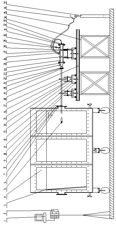
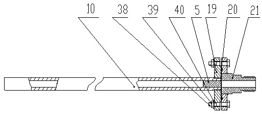
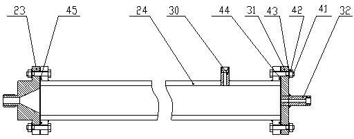
[0021] Such as figure 1 , figure 2 , image 3 As shown, the present invention includes industrial control computer 1, high-speed camera 2, rubber baffle 3, water tank 4, water tank flange 6, water tank flange cover plate 8, launch tube snap ring 9, launch tube 10, two rails 18, Launching pipe flange 19, pipe valve connector 21, solenoid valve 22, valve cylinder connector 23, high pressure cylinder 24, needle valve 26, cylinder flange cover plate 31, trolley support frame 34 and high pressure gas cylinder 37; water tank 4 front There is an observation window, a rubber baffle 3 is placed on one side of the water tank 4, and a round nozzle is opened on the other side of the water tank 4, and a water tank flange 6 is welded on the round nozzle, and the water tank flange 6 is installed with a water tank sealing ring in sequence 7 and the water tank flang...


PUM


Abstract

The invention discloses an experimental device of interaction of a horizontal supercavity and a free surface. A rubber baffle is arranged on one side in a water tank, one end of a transmitting tube penetrates through the water tank, the other end of the transmitting tube is connected with a high-pressure cylinder through a solenoid valve, and a high-pressure gas bottle is connected with an air inlet of the cylinder through a reducing valve and a needle valve; and the transmitting tube and the high-pressure cylinder can be moved in a dolly; a camera of a high rate photographic instrument faces an observation window of the water tank, and the high rate photographic instrument is connected with an industrial computer. An experimental bluff body driven by high pressure gas is accelerated in the transmitting tube, ruptured and shot into water, and a three-dimensional flow field generated along with a supercavity gradually appears around the experimental bluff body. A supercavity forming, developing and collapsing process when the high speed bluff body enters the water and an interaction process of the supercavity and the free surface are photographed with a high-speed photography technique so as to facilitate researches on a motion law of the steady state supercavity and the unsteady state supercavity in water, water trajectories and the like. The experimental device disclosed by the invention can be used for studying a whole forming process of the supercavity at different water depths and different angles.

Description

technical field [0001] The invention relates to an accelerated launching device for an underwater vehicle in the field of hydrodynamics, in particular to an experimental device for the interaction between a horizontal supercavitation and a free surface. Background technique [0002] The resistance of underwater vehicles is about 800-1000 times that of aerial vehicles, which leads to the common defects of slow speed, short range and low accuracy in traditional underwater weapons. In order to increase the speed of underwater vehicles and improve the combat performance of underwater weapons, two technical approaches are generally adopted: increasing the driving force and reducing the navigation resistance. Because under normal circumstances, the speed of the underwater vehicle can only be increased by 1 times when the thrust is increased by 8 times. Therefore, countries have carried out a lot of research work to find ways to reduce the resistance of underwater vehicles, and th...

Claims


Application Information

Patent Timeline
Patent Type & Authority Applications(China)
IPC IPC(8): G01M10/00
Inventor 施红辉周素云胡俊辉胡青青
Owner ZHEJIANG SCI-TECH UNIV
Learn More