Gas purifying device

A gas purification device and gas technology, applied in chemical instruments and methods, using liquid separation agents, and separation of dispersed particles, can solve problems such as environmental pollution, flue fouling, and high cost, and achieve cost reduction and emission reduction The effect of increasing the amount and contact area

Inactive Publication Date: 2012-09-05
周宗云
View PDF8 Cites 0 Cited by
  • Summary
  • Abstract
  • Description
  • Claims
  • Application Information

AI Technical Summary

Problems solved by technology

[0002] Public canteens and restaurant catering kitchens will produce harmful exhaust gas that will produce a large amount of volatile oil and impurities during cooking. The direct discharge of this oil exhaust gas will cause serious environmental pollution and harm human health. This grease exhaust gas will produce scaling in the exhaust duct prone to fire hazard
The existing electrostatic deoiling technology is expensive, the effect is unstable, cleaning is inconvenient, the operating cost is too high, the burden on users is too heavy to accept, it cannot meet the national energy saving requirements, and it is not conducive to wide application
The general wet electric deoiling device is not effective and cannot meet the national environmental protection industry emission requirements

Method used


Image

  • Gas purifying device
  • Gas purifying device

Examples


Embodiment Construction

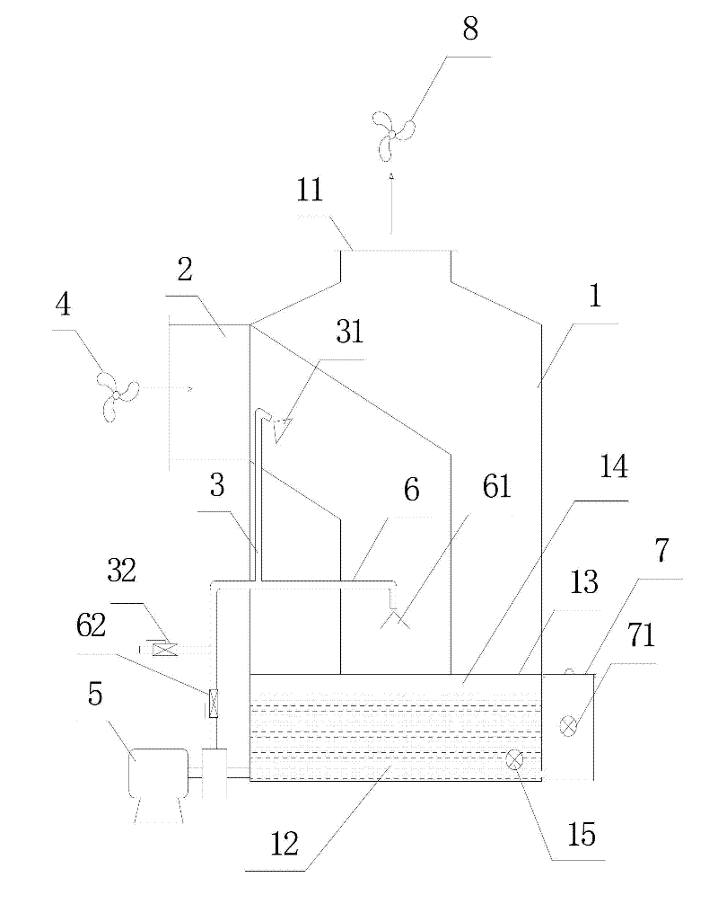
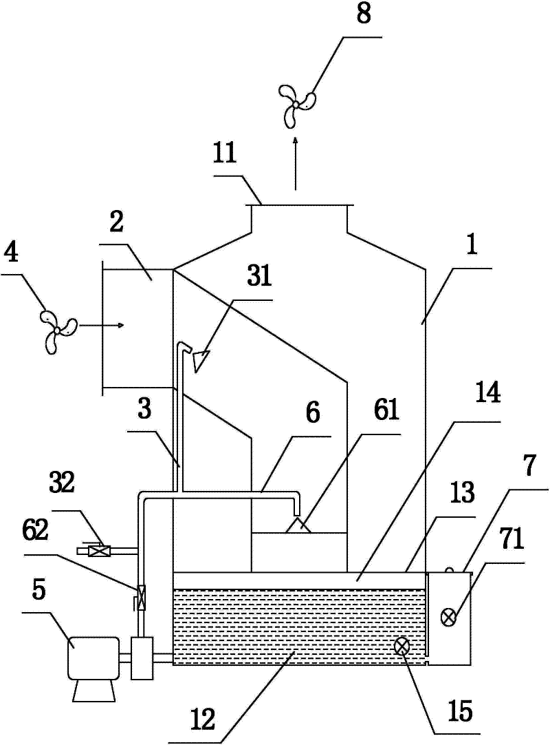
[0024] Such as figure 1 Shown, a kind of gas purification device comprises:

[0025] An outer tower 1, an exhaust port 11 is arranged on the top of the outer tower, a liquid storage chamber 12 is arranged at the bottom, a gas distribution net 13 is arranged above the liquid storage chamber 12, and a purification chamber 14 is formed between the gas distribution net and the liquid surface of the liquid storage chamber ;

[0026] A backflow device 2, the backflow device is embedded into the outer tower 1, and the end of the backflow device is attached to the gas distribution network 14;

[0027] A liquid inlet pipe 3, the liquid inlet end of the liquid inlet pipe 3 communicates with the liquid storage chamber 12, the liquid outlet end is nested into the inclined section of the backflow device, and the first liquid separation cone 31 is provided at the liquid outlet port;

[0028] The gas to be purified is passed into the backflow device 2 under the action of a fan 4, and the p...


PUM


Abstract

The invention discloses a gas purifying device which is simple, practical, lower in cost, and wide in application range, and can be used for purifying different waste gases. The gas purifying device comprises an outer tower, a backflow device and a liquid inlet pipe, wherein a gas outlet is arranged at the upper part of the outer tower, the bottom of the outer tower is provided with a liquid storing cavity, a gas dividing net is arranged above the liquid storing cavity, and a purifying cavity is formed between the gas dividing net and the liquid surface of the liquid storing cavity; the tail end of the backflow device is connected with the gas dividing net; one end of the liquid inlet pipe is communicated with the liquid storing cavity, the other end of the liquid inlet pipe is embedded into the backflow device, and the liquid inlet pipe is provided with a cone-hopper-shaped liquid outlet end; the gas to be purified enters into the backflow device under the action of a fan, and the purifying liquid in the liquid storing cavity flows along with the liquid inlet pipe under the action of a circulating pump, so that the gas which is sprayed out of the liquid outlet end and is guided to enter into the backflow device downwards moves in an acceleration way, and flows into the liquid storing cavity through the gas dividing net, therefore, a first circulating system can be formed; and the gas downwards moves along with the backflow device, is evenly filtered by the gas dividing net, and is evenly sprayed to the purifying cavity and sufficiently reacted with the purifying liquid to be purified, and the purified gas is discharged from the gas outlet through a hollow cavity arranged between the outer wall of the backflow device and the inner wall of the outer tower.

Description

technical field [0001] The invention relates to a gas purification device. Background technique [0002] Public canteens and restaurant catering kitchens will produce harmful exhaust gas that will produce a large amount of volatile oil and impurities during cooking. The direct discharge of this oil exhaust gas will cause serious environmental pollution and harm human health. This grease exhaust gas will produce scaling in the exhaust duct It is easy to cause fire hazard. The existing electrostatic deoiling technology is expensive, the effect is unstable, cleaning is inconvenient, the operating cost is too high, the burden on users is too heavy to accept, it cannot meet the national energy saving requirements, and it is not conducive to wide application. The general wet electric deoiling device is not effective and cannot meet the national environmental protection industry emission requirements. Contents of the invention [0003] Aiming at the deficiencies of the prior ar...

Claims


Application Information

Patent Timeline
Patent Type & Authority Applications(China)
IPC IPC(8): B01D53/78B01D47/06
Inventor 周宗云
Owner 周宗云
Why Eureka
Try Eureka