Drying device

A technology of drying device and drying tank, which can be applied to washing devices, household clothes dryers, textiles and papermaking, etc., and can solve problems such as labor-intensive

Active Publication Date: 2012-09-05
PANASONIC CORP
View PDF6 Cites 2 Cited by
  • Summary
  • Abstract
  • Description
  • Claims
  • Application Information

AI Technical Summary

Problems solved by technology

This can lead to labor intensive maintenance of the dryer

Method used


Image

  • Drying device
  • Drying device
  • Drying device

Examples


Embodiment Construction

[0038] Next, one embodiment of the drying device will be described with reference to the drawings. In addition, terms such as "up", "down", "left" or "right" used in the following description are only used for clear description, and are not used to limit the principle of the drying device.

[0039] (The overall structure of the dryer)

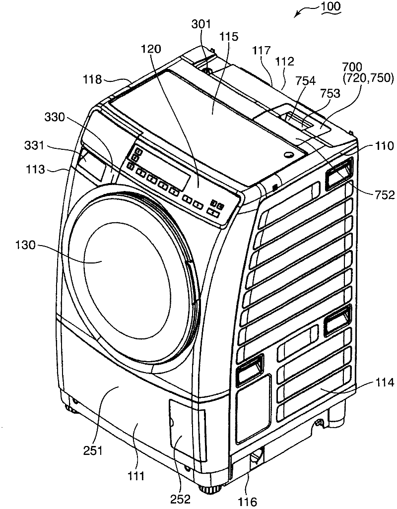
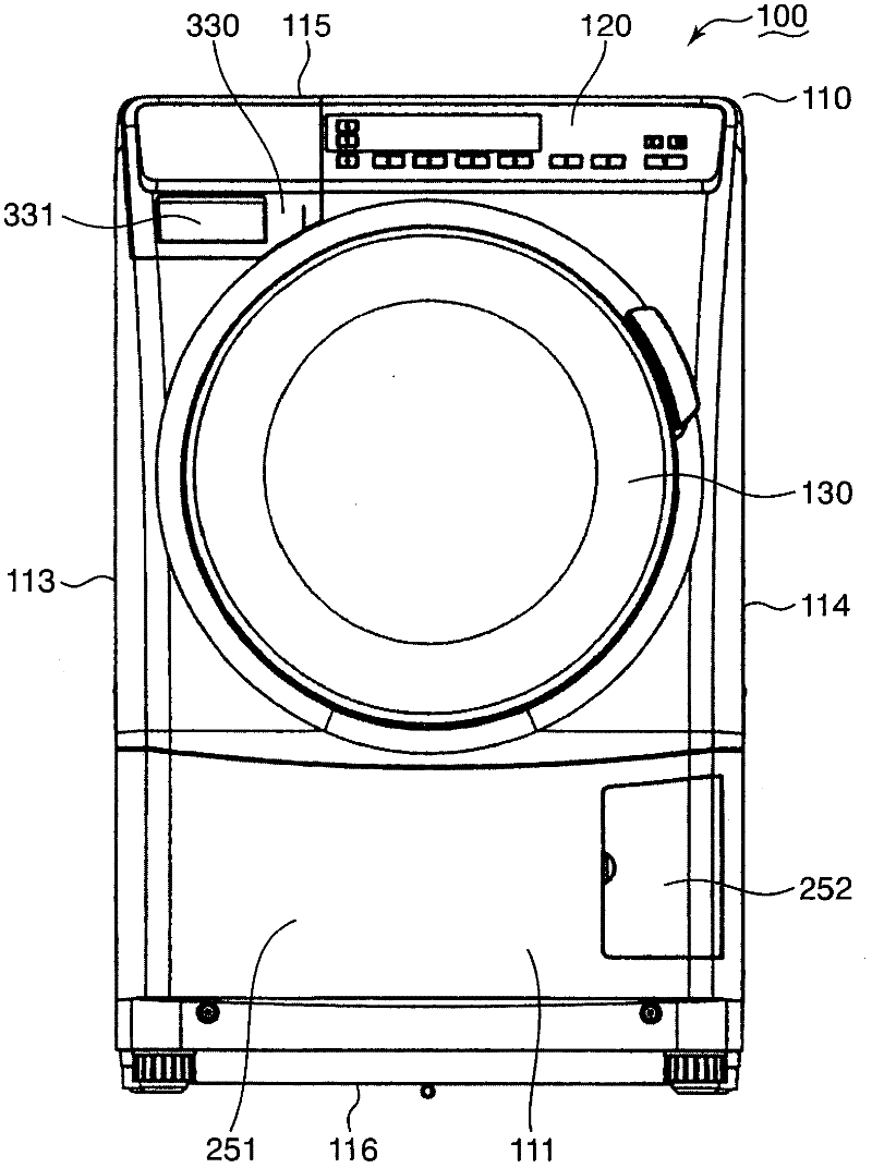
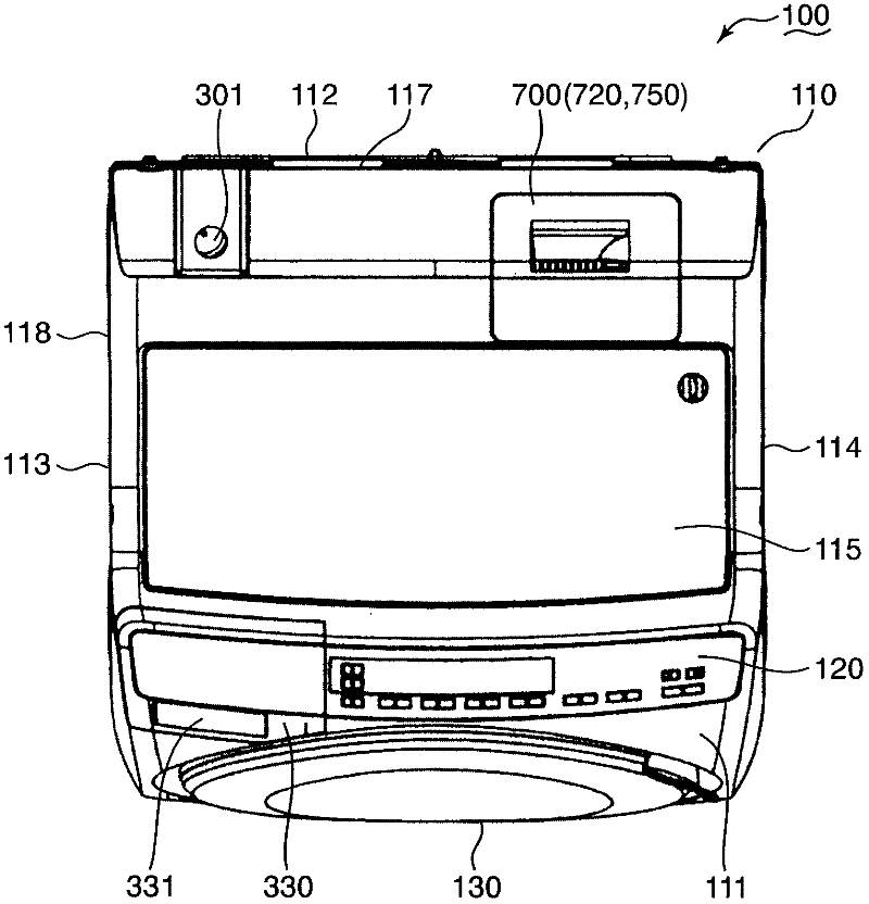
[0040] figure 1 It is a schematic perspective view of a dryer that has a laundry function in addition to a drying function. figure 2 yes figure 1 Front view of dryer shown. image 3 yes figure 1 Top view of dryer shown.

[0041] In this embodiment, Figure 1 to Figure 3 The illustrated dryer 100 is exemplified as a drying device for drying laundry. Instead, a dryer that does not have a laundry function can also be used as a drying device.

[0042] The dryer 100 includes a substantially rectangular box-shaped main housing 110 . The main housing 110 includes a front wall 111 , a rear wall 112 opposite to the front wall 111 , and a left ...


PUM


Abstract

The invention provides a drying device used for drying clothes, comprising: a drying groove used for accommodating the clothes; and a circulating system circulating drying air drying the clothes in the drying groove, wherein, the circulating system comprises a dehumidifying part dehumidifying the drying air, and a downstream part into which the drying air after dehumidification by the dehumidifying part flows, the dehumidifying part comprises a guide pipe with an inner surface guiding dehumidifying water for dehumidifying the drying air, the guiding pipe comprises an air outlet for exhausting the drying air, the downstream part is deviated from a direction perpendicular to the opening direction of the air outlet, allowing vision through the air outlet to reach the inner surface. According to the above structure, efficient maintenance work can be realized.

Description

technical field [0001] The invention relates to a drying device for drying clothes. Background technique [0002] A drying device such as a dryer that dries clothes or a washer dryer that not only has a drying function but also has a washing function, generally includes a dehumidifier that dehumidifies the dry air used for drying the clothes. [0003] Patent Document 1 discloses a tubular heat exchanger used in a washing and drying machine. This heat exchanger is used to dehumidify the drying air. [0004] Due to the drying process of blowing dry air to the clothes, lint (dust components such as broken threads) is generated from the clothes. The lint is circulated within the dryer by the drying air. The drying air passes through a tubular heat exchanger. [0005] In the heat exchanger, water is supplied in addition to drying air. As a result of heat exchange with water, the drying air is dehumidified. [0006] The dehumidified water for drying air is supplied to the he...

Claims


Application Information

Patent Timeline
IPC IPC(8): D06F58/02D06F58/04
Inventor 中西健浩井上贵裕小谷淳二
Owner PANASONIC CORP
Why Eureka
Try Eureka