Solar panel support

A technology of photovoltaic panels and supports, applied to the support structure of photovoltaic modules, photovoltaic modules, photovoltaic power generation, etc., can solve problems such as disappearance and high cost, and achieve easy maintenance operations, simple maintenance operations, and simple and easy maintenance operations Effect

Inactive Publication Date: 2020-07-14
LS ELECTRIC CO LTD
View PDF4 Cites 0 Cited by
  • Summary
  • Abstract
  • Description
  • Claims
  • Application Information

AI Technical Summary

Problems solved by technology

[0012] However, for the buoyancy-integrated photovoltaic panel support of the prior art, there are the following inconveniences: in the case of damage to the buoyancy body 3, it is necessary to replace the entire buoyancy body 3, which requires a higher cost; When the buoyancy body 3 is removed, the support force of the corresponding part will disappear, so it is necessary to set up a corresponding temporary support structure, etc.

Method used


Image

  • Solar panel support
  • Solar panel support
  • Solar panel support

Examples


Embodiment Construction

[0065] Hereinafter, preferred embodiments of the present invention will be described with reference to the accompanying drawings. This is a detailed description to enable those of ordinary skill in the art to implement the invention easily, and this does not mean to limit the technical idea and scope of the present invention.

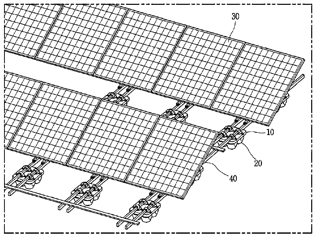
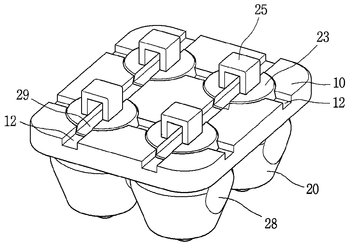
[0066] figure 2 is a perspective view of a photovoltaic panel support in one aspect of the present invention, image 3 yes figure 2 A perspective view of the buoyant body shown, Figure 4 yes image 3 side view, Figure 5 and Figure 6 is the perspective view and the bottom plan view of the parent buoyancy body, Figure 7 is a perspective view of the sub-buoyancy body. The photovoltaic panel support body of each embodiment of the present invention will be described in detail with reference to the accompanying drawings.

[0067] The photovoltaic panel support body in one aspect of the present invention is characterized in that it includes a buoy...


PUM


Abstract

The present invention has been devised to solve the problem mentioned above and a purpose thereof is to provide a solar panel support having a buoyant body, which has excellent buoyancy retention, enables easy maintenance, and even during maintenance, can maintain maximum supportability. A solar panel support according to one aspect of the present invention comprises a buoyant body for supportinga solar panel, wherein the buoyant body comprises: a parent buoyant body including a coupling hole formed therethrough; and a child buoyant body detachably and fittedly inserted to the coupling hole.

Description

technical field [0001] The invention relates to a photovoltaic panel support, and more specifically, to a photovoltaic panel support applied to a photovoltaic power generation system. Background technique [0002] Generally, a photovoltaic power generation system (device) is a device that converts solar energy (Photovoltaic Energy) into electric energy (Electric energy) by using a photovoltaic cell and generates electricity. [0003] This type of photovoltaic power generation system has been installed on the ground or on the roof of a building in the past, but in consideration of securing the site and the efficiency of the power generation device, the number of installations on water is increasing. In the case of installing photovoltaic power generation devices on water, there are advantages such as reducing compensation and cost issues involved in land acquisition, reducing friction with residents, and improving power generation efficiency by utilizing the cooling effect of...

Claims


Application Information

Patent Timeline
Patent Type & Authority Applications(China)
IPC IPC(8): H02S20/00H02S30/10H01L31/042B63B35/44
CPCH02S20/00B63B35/44H01L31/042Y02E10/50B63B2035/4453B63B3/08B63B35/38F24S20/70F24S2020/14Y02E10/47H02S10/40H02S30/10
Inventor 梁承必元昌燮
Owner LS ELECTRIC CO LTD
Why Eureka
Try Eureka