Protection device for a wave energy generating device

A power generation device and protection device technology, which is applied in wind power generation, ocean power generation, hydropower generation, etc., can solve the problem that wave power generation devices are easily covered or polluted by seabed mud and other sundries, and increase the wave power generation devices to float out of the sea Difficulty in restoring power generation, lack of anti-strike protection devices, etc., to achieve good protection effect, prevent bad weather, and good fixation effect

Inactive Publication Date: 2018-10-09
NINGBO UNIV +1
View PDF7 Cites 1 Cited by
  • Summary
  • Abstract
  • Description
  • Claims
  • Application Information

AI Technical Summary

Problems solved by technology

The real sea test proves that this method can protect the device, but its disadvantage is that the wave power generation device is easily covered or polluted by debris such as seabed silt, which greatly increases the difficulty of the wave power generation device surfacing and restoring power generation.
At the same time, in bad weather, the wave energy power generation device cannot work normally, and the energy of the seabed surge and the wind energy in bad weather cannot be better utilized.
[0004] For example, the application number is "201210099823.5", and the invention title is "one-way damping wave energy generation device", there is no protection device against various severe weather, and at the same time, in general severe weather, new wind energy cannot be used generate electricity

Method used


Image

  • Protection device for a wave energy generating device
  • Protection device for a wave energy generating device
  • Protection device for a wave energy generating device

Examples


Embodiment 1

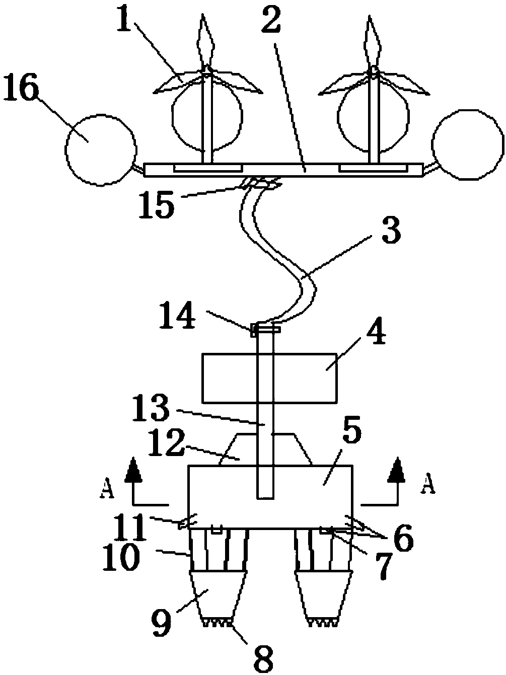
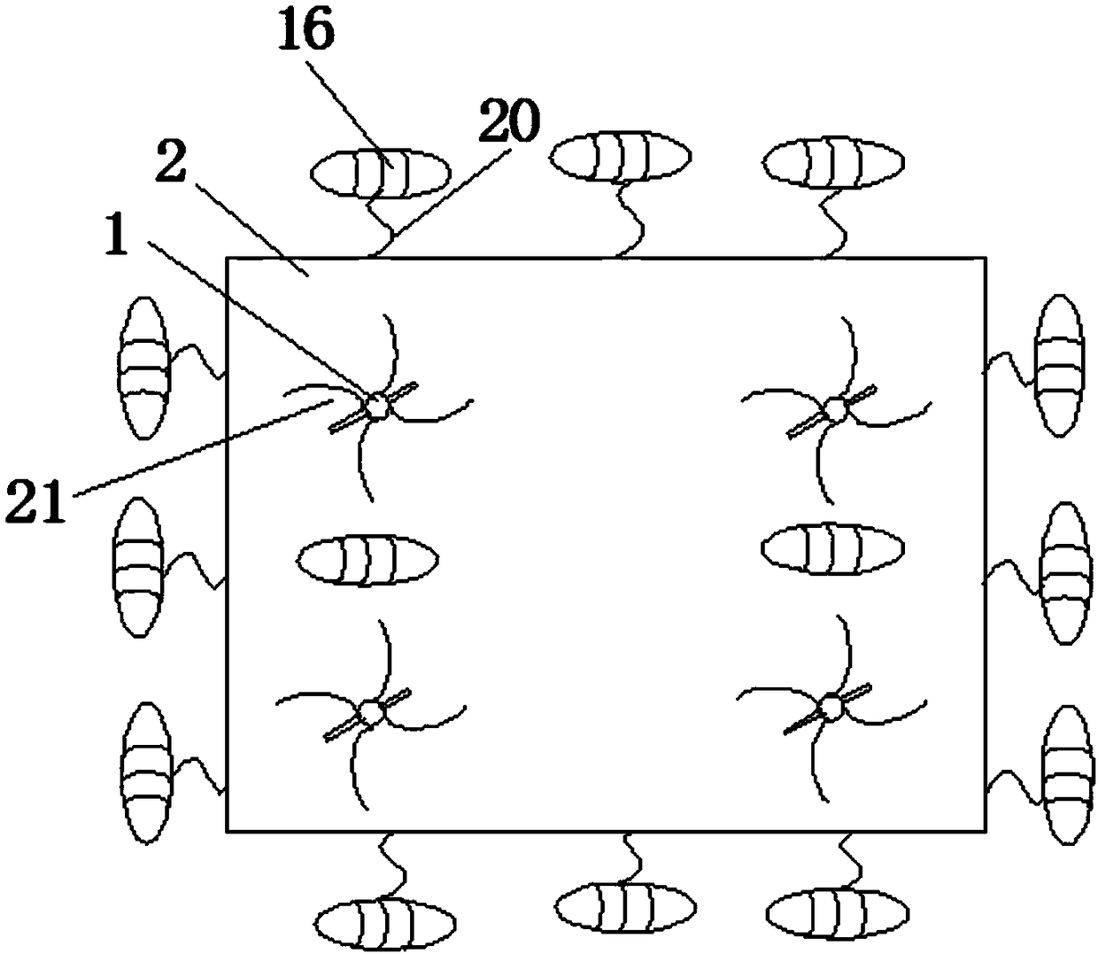
[0032] Embodiment one: if Figures 1 to 6 As shown, the present invention includes a wave energy generating device 4, the middle part of the wave energy generating device 4 is provided with an air inlet and water inlet pipe 13, one end of the air inlet and water inlet pipe 13 is connected to one end of the hose 3, and the other end of the air inlet and water inlet pipe 13 is arranged on Inside the air intake and drainage cabin, the air intake and drainage cabin is arranged at the bottom of the wave energy generating device 4, the other end of the hose 3 is provided with a floating pad 2, and floating balls 16 are provided around the floating pad 2 through connecting pieces 20, so The upper surface of the floating pad 2 is provided with a floating ball 16 and a wind generator, and the inside of the floating pad 2 is provided with an electric energy conversion and electric energy collection device. The connection between the hose 3 and the floating pad 2 is provided with a first co...

Embodiment 2

[0036] Embodiment two: if Figure 1-8 As shown, the present invention includes a wave energy generating device 4, the middle part of the wave energy generating device 4 is provided with an air intake and water inlet pipe 13, one end of the air intake and water inlet pipe 13 is connected to the hose 3, and the other end of the air intake and water inlet pipe 13 is arranged on the air intake and drainage Inside the cabin, the air intake and drainage cabin is arranged at the bottom of the wave energy generating device 4, the other end of the hose 3 is provided with a floating pad 2, and floating balls 16 are provided around the floating pad 2 through connectors 20, and the floating pad 2 The upper surface is provided with a floating ball 16 and a wind generator, and an electric energy conversion and electric energy collection device is provided inside the floating pad 2, and a first control valve 15 is provided at the connection between the hose 3 and the floating pad 2. A second...

Embodiment 3

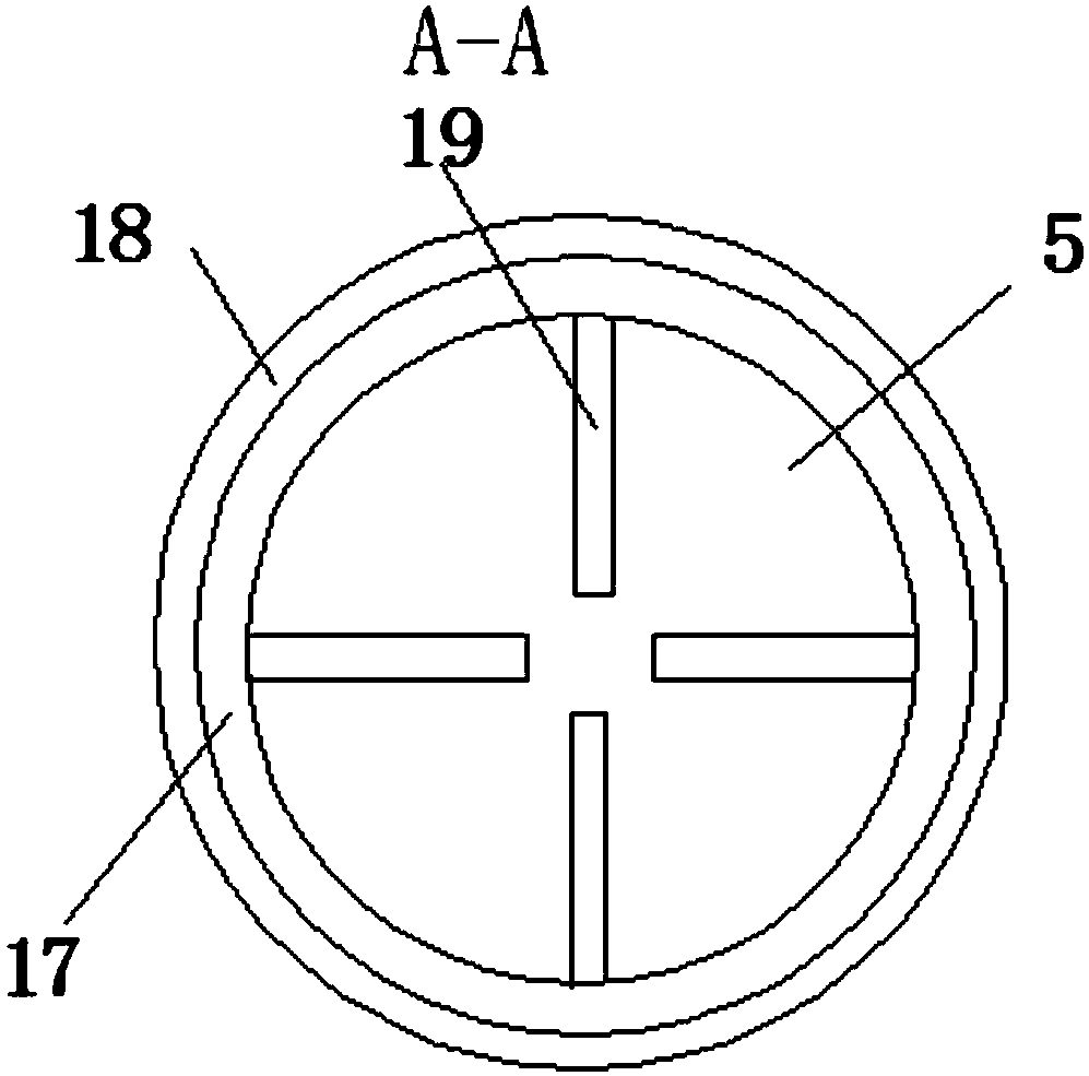
[0042] Embodiment three: as Figure 1-9 As shown, the present invention includes a wave energy generating device 4, the middle part of the wave energy generating device 4 is provided with an air intake and water inlet pipe 13, one end of the air intake and water inlet pipe 13 is connected to the hose 3, and the other end of the air intake and water inlet pipe 13 is arranged on the air intake and drainage Inside the cabin, the air intake and drainage cabin is arranged at the bottom of the wave energy generating device 4, the other end of the hose 3 is provided with a floating pad 2, and floating balls 16 are provided around the floating pad 2 through connectors 20, and the floating pad 2 The upper surface is provided with a floating ball 16 and a wind generator, and an electric energy conversion and electric energy collection device is provided inside the floating pad 2, and a first control valve 15 is provided at the connection between the hose 3 and the floating pad 2. A seco...


PUM


Abstract

The invention discloses a protecting device for a wave-energy power generating device. The protecting device comprises the wave-energy power generating device, an air inlet and water inlet pipe is arranged in the middle of the wave-energy power generating device, one end of the air inlet and water inlet pipe is connected with a hose, the other end of the air inlet and water inlet pipe is arranged in an air inlet and water drainage cabin which is arranged at the bottom of the wave-energy power generating device, a floating mat is arranged at the other end of the hose, floating balls are arranged all around the floating mat through connecting parts, floating balls and wind power generators are arranged on the upper surface of the floating mat, and a power conversion and power collection device is arranged in the floating mat; and drainage pipes are arranged on the air inlet and water drainage cabin, two fixing blocks are connected to the bottom of the air inlet and water drainage cabin through fixing block anchor chains, and multiple stabilizing blocks are arranged at the bottom of each fixing block. The protecting device for the wave-energy power generating device has the advantages of being capable of being suitable for bad weather, capable of better utilizing wind energy under bad weather and achieving multiple power generating modes, higher in safety and longer in service life.

Description

technical field [0001] The invention belongs to the technical field of new energy development and utilization, and in particular relates to a protection device for a wave energy power generation device which is suitable for multi-purpose and multi-mode power generation in bad weather. Background technique [0002] Environmental pollution and resource depletion are becoming more and more serious in today's world. The development and utilization of new energy is an inevitable requirement for the development of human society and the development of the world economy. Wave energy is a renewable and clean energy with huge reserves, and the development and utilization of wave energy has broad prospects for development. At present, the mainstream of research and development of wave energy utilization devices is the floating wave energy generation device. But catastrophic climates such as typhoons are extremely destructive to such devices. It is an inevitable requirement for the ap...

Claims


Application Information

Patent Timeline
Patent Type & Authority Patents(China)
IPC IPC(8): F03B13/14F03B11/00F03D9/25
CPCF03B11/00F03B13/14F03D9/008Y02E10/20Y02E10/30Y02E10/72
Inventor 李广年黄兴
Owner NINGBO UNIV
Why Eureka
Try Eureka