Buoyancy automatic control valve

A buoyancy-type, self-control valve technology, applied in the direction of the valve details, valve device, valve shell structure, etc., can solve the problems of high processing precision, abnormal use, easy failure, etc., and achieve a compact and reasonable overall structure. The effect of simplification and volume reduction

Active Publication Date: 2015-07-29
佛山市顺德区中江节能电子有限公司
View PDF6 Cites 1 Cited by
  • Summary
  • Abstract
  • Description
  • Claims
  • Application Information

AI Technical Summary

Problems solved by technology

[0003] For toilet water storage tanks, the current common solution is to use buoyancy-type self-control valves to control the water level, such as common items such as toilet water storage tanks and water towers. The advantages of using buoyancy-type self-control valves to realize automatic quantitative water supply are: The cost is low, but also because of its many parts, complex structure, and high processing precision requirements, it is prone to failure and cannot be used normally

Method used


Image

  • Buoyancy automatic control valve
  • Buoyancy automatic control valve
  • Buoyancy automatic control valve

Examples


Embodiment 1

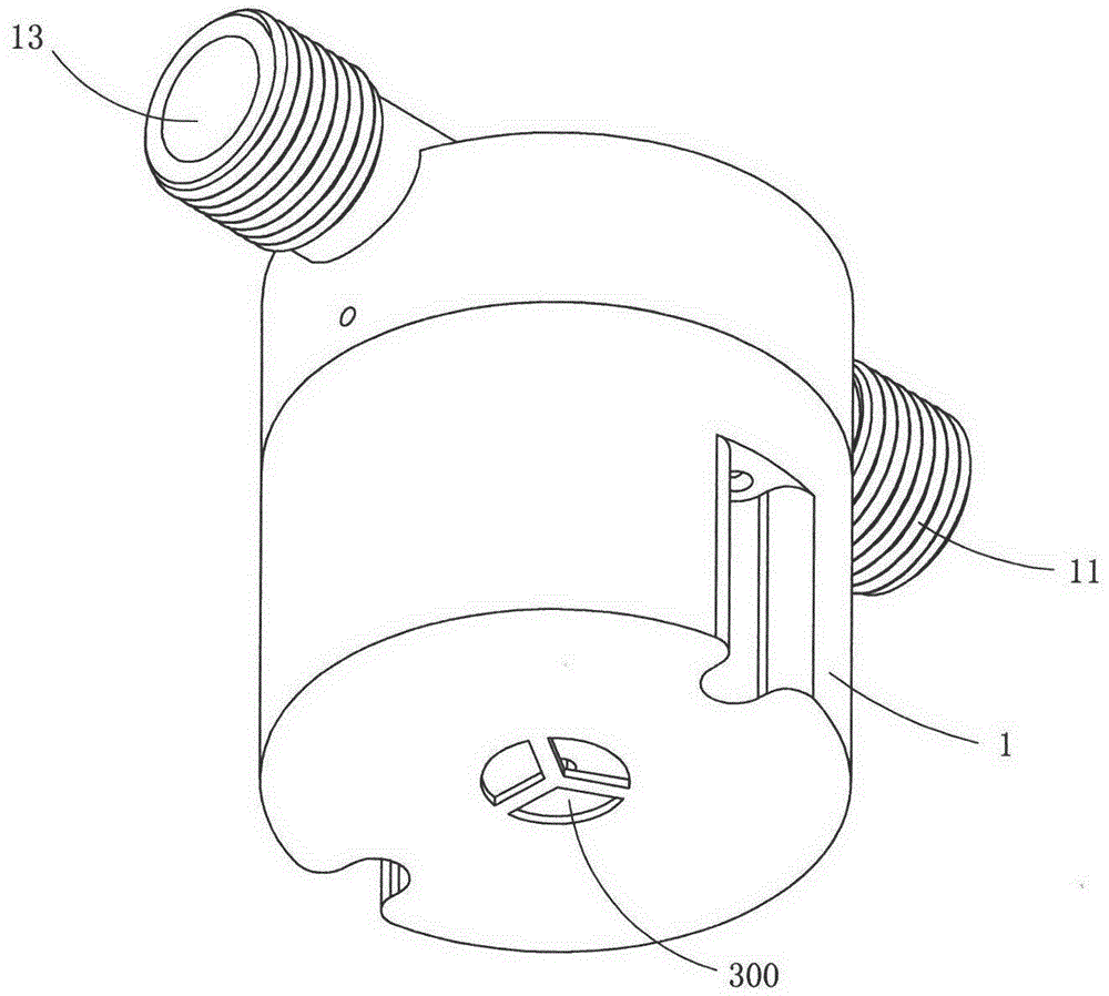
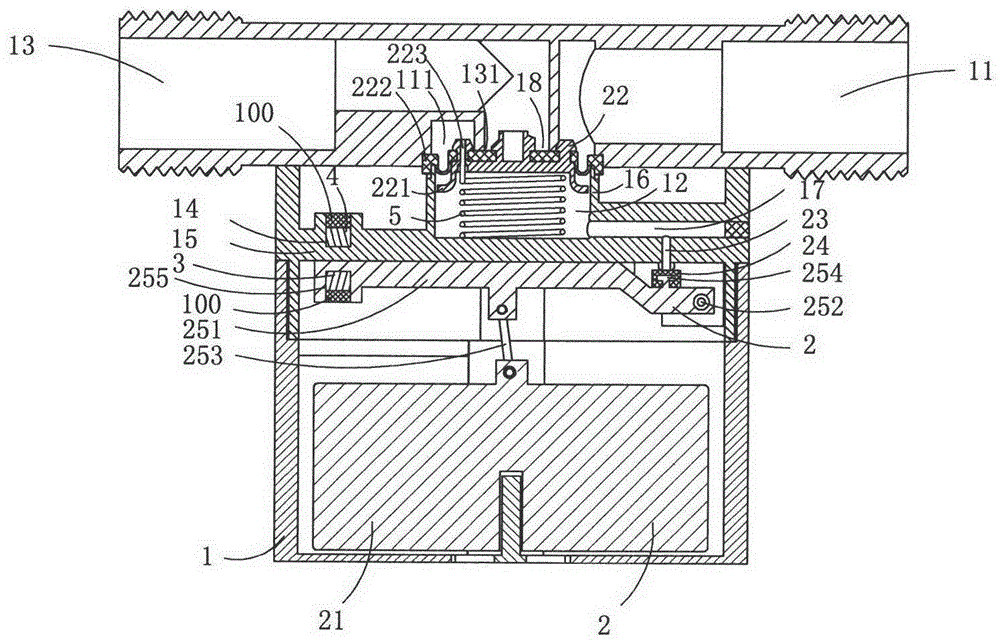
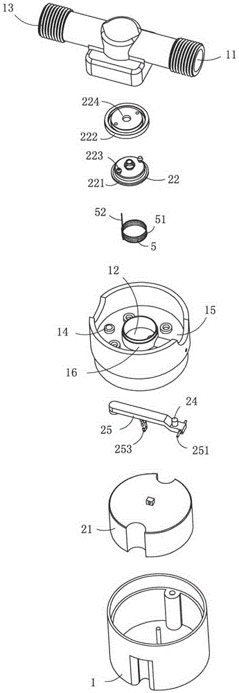
[0022] Figure 1 to Figure 4 A first embodiment of the invention is shown in which, figure 1 It is a schematic diagram of a three-dimensional structure of the present invention; figure 2 for figure 1 A sectional view of the buoyancy self-control valve shown; image 3 for figure 1 An exploded diagram of the buoyancy self-control valve shown; Figure 4 for figure 1 An exploded view of the buoyancy control valve shown when viewed from another angle.

[0023] This embodiment is a buoyancy type self-control valve, see Figure 1 to Figure 4 , including a valve body 1, and a buoyancy on-off component 2 for on-off valve body 1; the valve body 1 includes a water inlet channel 11, a control chamber 18, a water inlet hole 300 and a water outlet channel 13; The center of the control chamber 18 is provided with a pipe body 131 as the water inlet 132 of the water outlet channel 13, and the area between the outer wall of the pipe body 131 and the inner wall of the pressure regulating...

Embodiment 2

[0035] This embodiment is basically the same as Embodiment 1, the difference is that: the water inlet hole 300 on the valve body 1 in this embodiment is no longer like Embodiment 1, only several through holes 300 are set on the valve body, and In Embodiment 1, a through hole is provided, and a convex pipe protruding from the valve body with an external thread is provided. The convex pipe can be used as a pipe joint for connecting with an external water pipe. This structure can make the valve body Embodiments can be used without being placed in a water storage container.


PUM


Abstract

The invention discloses a buoyancy-type automatic control valve which comprises a valve body and a buoyancy-type on / off component, wherein the buoyancy-type on / off component comprises a floater for providing buoyancy, a pressure regulating chamber, a diaphragm-type valve core component, a pressure relieving channel, a seal plug, a linkage element, wherein the pressure regulating chamber is arranged above a control chamber; the diaphragm-type valve core component is arranged in the pressure regulating chamber and is used for separating the water inlet of a water outlet channel and the water outlet of a water inlet channel; the pressure relieving channel is used for communicating the pressure regulating chamber with the external environment; the seal plug is used for sealing and blocking a pressure relieving channel; the linkage element is used for linking the floater and the seal plug; the linkage element comprises a lever, a rotary shaft positioned at one end of the lever and a transmission element arranged at the middle part of the lever; the rotary shaft is arranged on the valve body; the seal plug is arranged on the lever and is positioned between the rotary shaft and the transmission element; and the transmission element drives the lever to rotate along the rotary shaft under the driving of the floater, and further drives the seal plug to perform the action of sealing and blocking the pressure relieving channel or opening the pressure relieving channel. The buoyancy-type automatic control valve provided by the invention is reasonable and compact in structure, has higher flexibility, and is difficult to damage.

Description

technical field [0001] The invention belongs to the technical field of structural design of automatic control valves, and in particular relates to a buoyancy type automatic control valve. Background technique [0002] Common open water storage containers, such as buckets, pots, vats, water towers, and toilet flushers, have a capacity problem when storing water, that is, when water is added to a certain level, the water will overflow , so certain measures are needed to prevent its overflow. For example, in a restaurant, when chefs cook, they use water very frequently, with a time limit, and the amount is relatively large. Their habitual practice is to put an open container under the faucet, and then turn on the tap all the time. Scooping from an open container will result in a large amount of water draining away. For this approach, there is no corresponding product on the market at present. [0003] For toilet water storage tanks, the current common solution is to use buoy...

Claims


Application Information

Patent Timeline
Patent Type & Authority Patents(China)
IPC IPC(8): F16K31/20F16K27/02F16K31/44
Inventor 陈银环
Owner 佛山市顺德区中江节能电子有限公司
Why Eureka
Try Eureka