Excavator bucket tooth

A technology of excavator bucket teeth and bucket teeth, which is applied in the field of bucket teeth and bucket teeth on excavators, can solve the problems of high cost of use, adverse effects of bucket teeth and tooth seats, and affecting work, and achieves strong practicability and wide application range wide effect

Active Publication Date: 2012-09-05
宁波市鄞州精铸五金厂
View PDF7 Cites 23 Cited by
  • Summary
  • Abstract
  • Description
  • Claims
  • Application Information

AI Technical Summary

Problems solved by technology

However, the connection structure between the bucket tooth and the tooth seat has the following disadvantages: due to the continuous shearing, torsion and other forces during use, the circlip will soon produce fatigue failure under the action of this alternating stress Even broken, so the service life is very short; at the same time, when replacing the pin, because the circlip is broken into the pin hole, it is difficult to hit the pin out with a hammer, usually by gas cutting and other methods first. Cut the tooth seat from the bucket of the excavator, then cut the joint between the bucket teeth and the tooth seat, and take out the pin and the retainer. Often, several or even ten sets of tooth seats need to be replaced during the life cycle of a pair of tooth seats. Several pairs of pins are expensive to use, which is cumbersome and inefficient
Although this structure can effectively prevent the clip spring and the pin from breaking due to the shear force concentrated in the middle of the pin during use, there are still problems. , so that the thickness of the pin hole at the mounting part of the tooth seat is relatively thinner. When the bucket tooth adopts the pin of the original technology (that is, the snap ring groove of the pin is opened in the middle of the pin), the shaking range of the bucket tooth is compared with the original The swaying range of the technical bucket teeth is greater, and the impact force on the pin is also greater, making it easier to break the pin
Although the existing technology has improved the impact resistance of the pin and prolonged a certain service life, the position of the circlip is always within the range of the pin holes at both ends of the gear seat, and the position of the circlip groove is still close to the middle of the pin. The bad part of the middle pin retaining ring is still weak, easy to break, and it is not easy to replace after breaking
In this way, when people use this kind of bucket teeth, the pins they choose must also be the pins in this technology. It is difficult for ordinary pins to be entrusted with this kind of bucket teeth. When the pins are in short supply, ordinary pins cannot be used to replace them, which will inevitably affect the work. If ordinary pins are used forcibly, it will have a certain adverse effect on the bucket teeth and tooth seats of the structure.

Method used


Image

  • Excavator bucket tooth
  • Excavator bucket tooth
  • Excavator bucket tooth

Examples


Embodiment 1

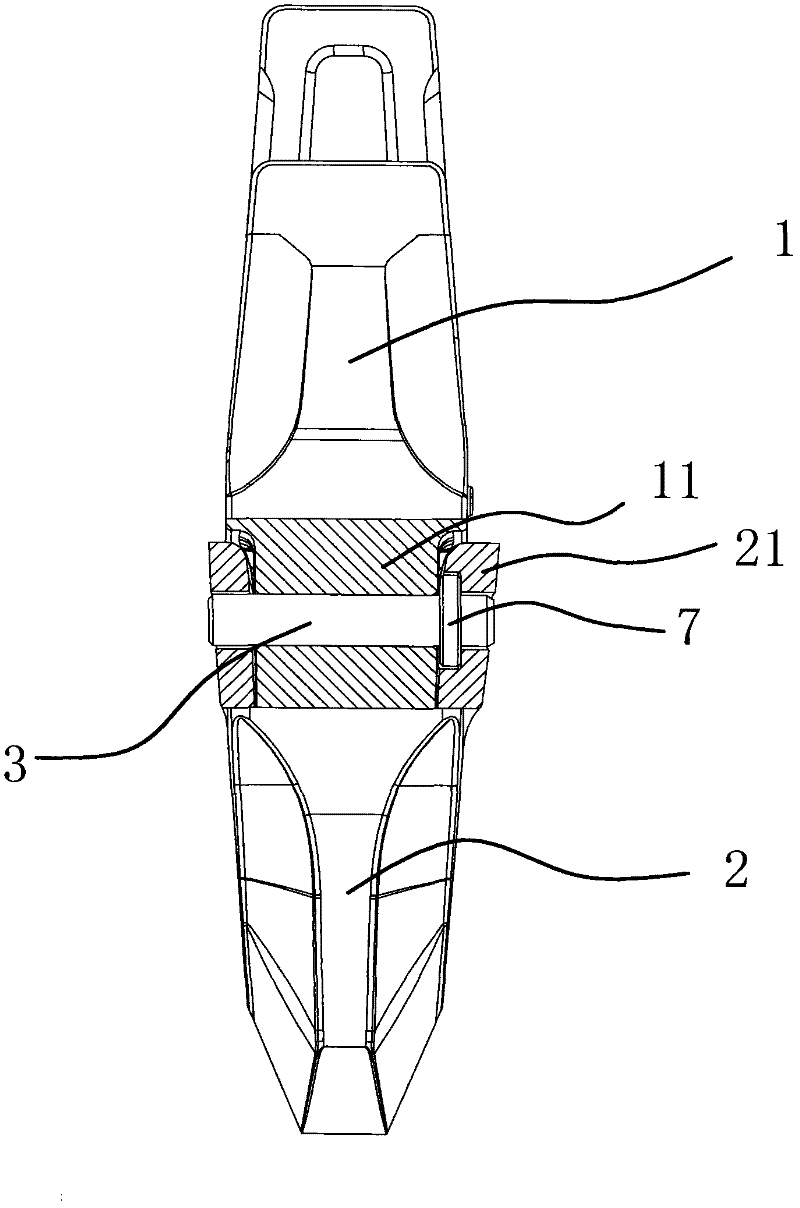
[0030] Such as figure 1 and figure 2 As shown, the bucket tooth of the excavator includes a tooth holder 1 with a mounting part 11 and a bucket tooth 2 with a connecting part 21. The installation part 11 of the tooth holder 1 is inserted between the two connecting parts 21 of the bucket tooth 2 and passed through the pin 3 and circlip 4 are fixedly connected, such as Image 6 As shown, the jumper 4 is a spiral jumper 4, and when the jumper 4 is stretched by the pin 3, the jumper 4 is stretched as a whole, so that when the jumper 4 is closed, the inner surface of the jumper 4 and the pin 3 Closely adhering, so that the clip spring 4 can be firmly clamped on the pin 3, and there is no gap between the clip spring 4 and the pin 3.

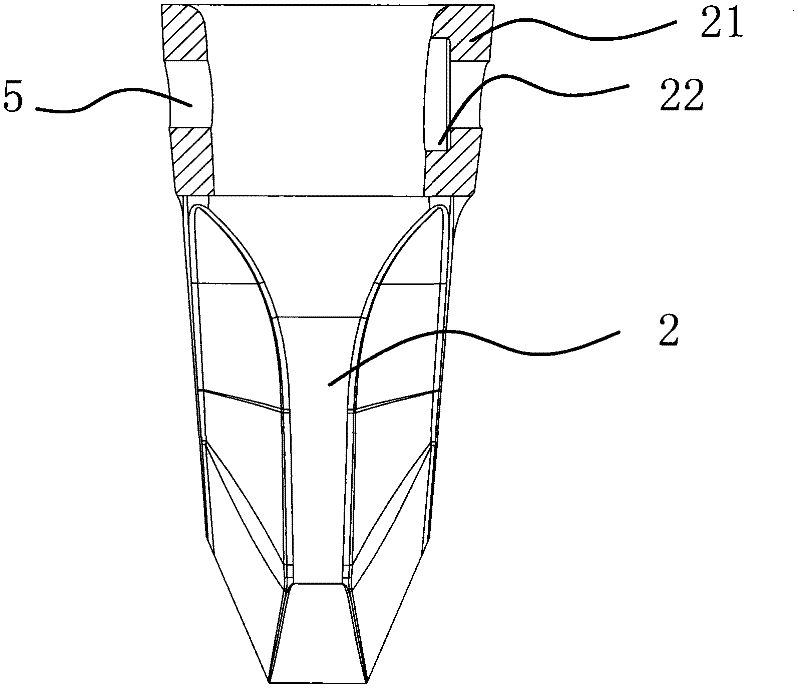
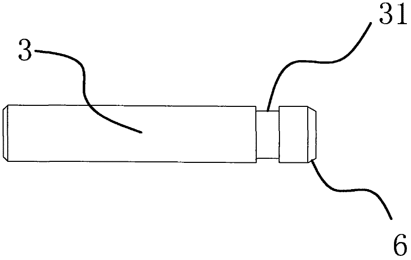
[0031] Such as Figure 3 to Figure 5As shown, an annular groove 31 is provided on the pin 3 and the circlip 4 is stuck in the annular groove 31, and a counterbore 22 is provided on the inner end surface of the pin hole 5 at either end of the bucket...

Embodiment 2

[0037] Such as Figure 7 to Figure 9 As shown, the structure and principle of this embodiment are basically the same as that of Embodiment 1, the difference lies in that the inner end faces of the pin holes 5 on the two connecting parts 21 of the bucket teeth 2 are provided with counterbore holes 22, and the counterbore holes 22 are uniformly arranged in the counterbore holes 22. A snap ring 4 is installed, which makes the connection between the bucket tooth 2 and the tooth holder 1 more firm. On the inner side of one of the annular grooves 31 on the pin 3, a chamfer 6 is provided, through which the chamfer 6 can make when the first jumper 4 falls into the annular groove 31 provided with the chamfer 6 When continuing to beat the hammer, the jump ring 4 can be disengaged from the annular groove 31 so that the pin 3 can continue to move forward.

[0038] When installing, firstly install the two snap springs 4 in the fixing seat 7 and place them in the counterbore 22 of the corr...


PUM


Abstract

The invention provides an excavator bucket tooth, and belongs to the technical field of machinery. The excavator bucket tooth solves the problems of high cost and low working efficiency of the conventional excavator bucket tooth. The excavator bucket tooth comprises a tooth seat with an installation part and a bucket tooth with connecting parts; each of the installation part of the tooth seat and the two connecting parts of the bucket tooth is provided with a pin hole on the same axial line; the installation part of the tooth seat is inserted into a space between the two connecting parts of the bucket tooth and fixedly connected with a snap spring through a pin; the pin is provided with an annular groove, and the snap spring is clamped in the annular groove; the inner end face of each pin hole in the bucket tooth is provided with a sunk hole; and the sunk holes and the annular groove in the pin are positioned on the same vertical plane, and the snap spring is positioned in the sunk holes. The excavator bucket tooth has the advantages of simple structure, long service life and wide application range.

Description

technical field [0001] The invention belongs to the technical field of machinery and relates to a bucket tooth, in particular to a bucket tooth suitable for an excavator. Background technique [0002] At present, excavators are often used in construction machinery. The excavator generally includes bucket teeth and tooth seats, and the two need to be fixed with pins, that is to say, the tooth seats and bucket teeth must have pins. Matching pin holes, while the tooth seat is welded on the bucket edge of the excavator. [0003] At present, there is a groove in the middle of the commonly used pin, and a C-shaped circlip is stuck on the groove. The inner diameter of the circlip is slightly larger than the diameter of the pin groove, and the outer diameter is slightly larger than the inner diameter of the pin hole. The pin penetrates into the pin hole of the tooth seat, and is locked by the friction force between the outer diameter of the circlip and the inner wall of the pin hol...

Claims


Application Information

Patent Timeline
Patent Type & Authority Applications(China)
IPC IPC(8): E02F9/28
Inventor 张灵
Owner 宁波市鄞州精铸五金厂
Why Eureka
Try Eureka