Aerodynamic force test device of flapping wing flying robot

A testing device and popular technology, applied in the direction of measuring force components, etc., to achieve the effect of reducing influence, reducing interference, and improving the accuracy of force measurement

Inactive Publication Date: 2014-07-02
SHENYANG INST OF AUTOMATION - CHINESE ACAD OF SCI
View PDF4 Cites 0 Cited by
  • Summary
  • Abstract
  • Description
  • Claims
  • Application Information

AI Technical Summary

Problems solved by technology

At present, there are no mature theoretical and empirical formulas for aerodynamics at low Reynolds numbers to follow

Method used


Image

  • Aerodynamic force test device of flapping wing flying robot
  • Aerodynamic force test device of flapping wing flying robot
  • Aerodynamic force test device of flapping wing flying robot

Examples


Embodiment 1

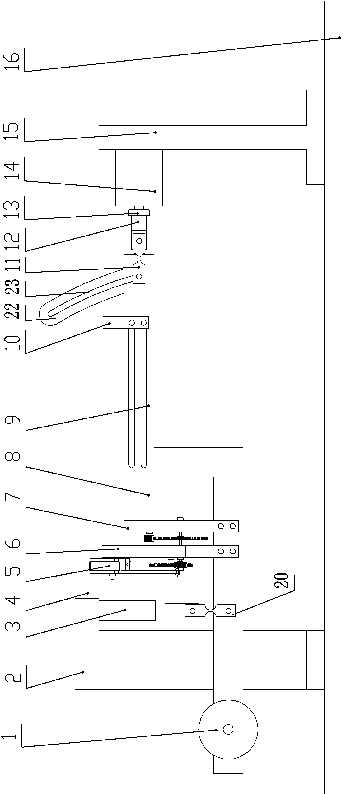
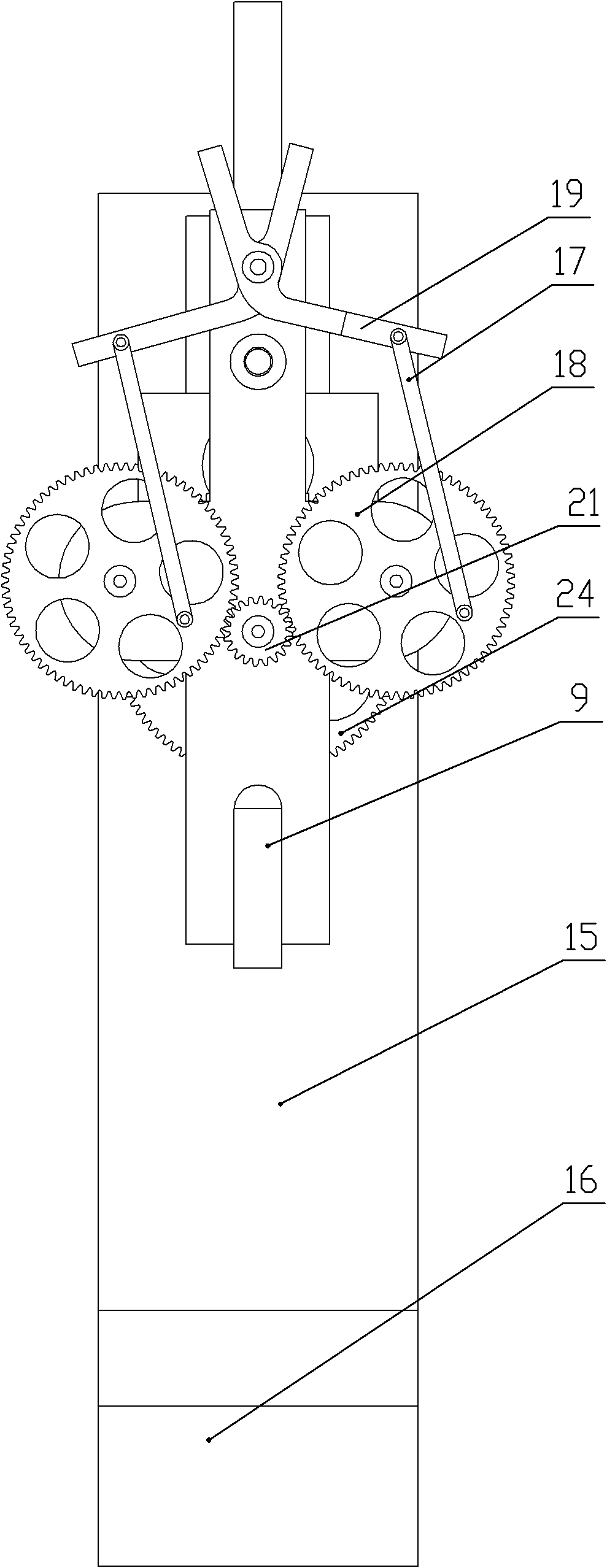
[0022] Embodiment 1: as figure 1 Shown, the present invention comprises fixed support 16, horizontal force sensor 15, vertical force sensor 3, test platform skeleton 9, drive motor 8, flutter device, hinge and wing width adjusting plate 10, described horizontal force sensor 14 and The support of the vertical force sensor 2 is respectively installed on the fixed support 16, and the test platform skeleton 9 is respectively connected with the connection bracket 12 on the horizontal and vertical force sensors 14 and 3 through the first and second flexible hinges 11, close to the vertical force sensor. The test platform skeleton 9 end of the sensor 3 is equipped with a counterweight 1, and the flutter device connected with the drive motor 8 is installed on the test platform skeleton 9 between the horizontal and vertical force sensors 14 and 3, and is close to the flutter on the vertical force sensor support 2. Diffuse switch 4 is installed at the actuator place to detect the flappi...


PUM


Abstract

The invention discloses an aerodynamic force test device of a flapping wing flying robot, belonging to the technical field of stress-strain tests. The device comprises a fixing frame, a horizontal force sensor, a vertical force sensor, a test platform skeleton, a drive motor, a flapping device and a wing width adjusting plate, wherein the brackets with the horizontal force sensor and the vertical force sensor are mounted on the fixing bracket respectively; the test platform skeleton is connected with the connection brackets on the horizontal and vertical force sensors through a first flexible hinge and a second flexible hinge respectively; a counter weight is mounted at the test platform skeleton end close to the vertical force sensor; the flapping device connected with the drive motor is mounted on the test platform skeleton between the horizontal and vertical force sensors; a diffuse reflection switch is mounted on the bracket with the vertical force sensor at a position close to the flapping device; and the horizontal and vertical force sensors, the diffuse reflection switch and the motor are connected with an electric control part respectively. According to the invention, the force test precision is improved, and the interference of the force not in the force test direction on the force sensors is reduced.

Description

technical field [0001] The invention belongs to the technical field of stress and strain testing, in particular to an aerodynamic testing device for a flapping-wing flying robot. Background technique [0002] In recent years, with the rapid development of MEMS technology, micro air vehicle has become a new research direction. Micro flapping wing aircraft has received more attention because it is easier to overcome the problems of aerodynamic efficiency and flight control at low Reynolds number, and has a broader development prospect. [0003] The California Institute of Technology (Caltech) was one of the first institutions to develop a flapping-wing flying robot. It jointly developed Microbat with the University of California (UCLA) and AeroVironment. The first prototype was tested in October 1998. It is the earliest bionic flapping wing flying robot. Microbat's body skeleton and wings are made of new super-strong composite materials. The wings imitate the wings of bats a...

Claims


Application Information

Patent Timeline
Patent Type & Authority Patents(China)
IPC IPC(8): G01L5/16
Inventor 李贵祥苏刚李洪谊
Owner SHENYANG INST OF AUTOMATION - CHINESE ACAD OF SCI
Why Eureka
Try Eureka