LED (light-emitting diode) support and manufacturing method thereof

A technology of an LED bracket and a manufacturing method, which is applied in the field of LED brackets, can solve the problems of easy loosening of conductive terminals, waterproof LED brackets, poor moisture-proof effect, and unsuitable use of outdoor products, etc., so as to achieve the effect of improving waterproofing.

Active Publication Date: 2012-09-05
东莞智昊光电科技有限公司
View PDF6 Cites 6 Cited by
  • Summary
  • Abstract
  • Description
  • Claims
  • Application Information

AI Technical Summary

Problems solved by technology

[0003] The conductive terminals of the above-mentioned LED bracket pass through the first and second insulating bodies in one direction at the same time, resulting in insufficient holding force of the first and second insulating bodies to the conductive terminals, making the conductive terminals easy to loosen
Moreover, the size of the LED bracket is very small. If the formed joint between the conductive terminal and the first and second insulating bodies is too small, the waterproof and moisture-proof effect of the LED bracket will be very poor, and it is not suitable for outdoor products.

Method used


Image

  • LED (light-emitting diode) support and manufacturing method thereof
  • LED (light-emitting diode) support and manufacturing method thereof
  • LED (light-emitting diode) support and manufacturing method thereof

Examples


Embodiment Construction

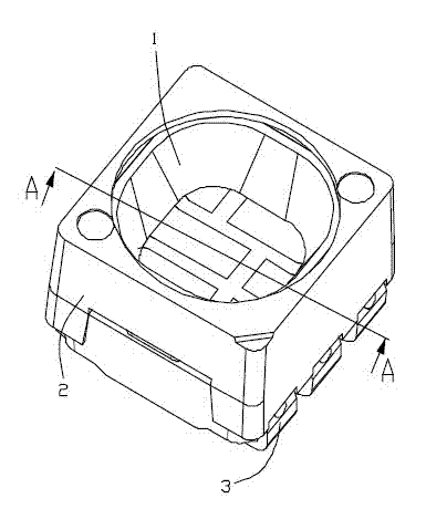
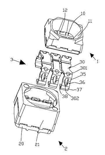
[0019] see Figure 1 to Figure 4 ,and Figure 9 As shown, the LED bracket of the present invention includes a first insulating body 1, a second insulating body 2 formed and covered outside the first insulating body 1, and at least one integrally formed in the first insulating body 1 and the second insulating body 2 A pair of conductive terminals 3 .

[0020] The first insulating body 1 includes a base plate 10 and a first peripheral wall 11 extending upward from the periphery of the base plate 10. The base plate 10 and the first peripheral wall 11 together form an open-ended enclosure for encapsulating LED chips. Accommodating cavity 12.

[0021] The second insulating body 2 includes a bottom 20 formed under the bottom plate 10 of the first insulating body 1 , and a second peripheral wall 21 extending upward from the bottom 20 and covering the first peripheral wall 11 .

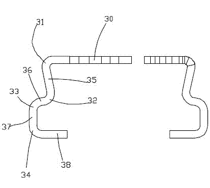
[0022] Each of the conductive terminals 3 includes a solid welding area 30, a first bent portion 31 for...


PUM


Abstract

The invention discloses an LED (light-emitting diode) support which comprises at least one pair of electric conducting terminals, a first insulation body and a second insulation body, wherein the first insulation body and the electric conducting terminals are molded into a whole; the second insulation body is molded outside the first insulation body; the first insulation body is provided with a containing cavity which is used for packaging an LED chip; each electric conducting terminal comprises a fixed welding region, a first extending part, a second extending part and a welding part, wherein the fixed welding part is exposed out of the bottom surface of the containing cavity; the first extending part is formed in the way that the fixed welding part is bent from the tail end to form a first bent part and then extends inwards at a certain inclined angle; the second extending part is formed in that way that the first extending part is bent from the tail end to form a second bent part and then extends outwards; the welding part is formed in the way that the second extending part is bent to form a third bent part and then extends; the fixed welding region is close to one end of the first bent part and is integrally molded into the first insulation body; and the first extending part and the second bent part are integrally molded in the second insulation body. The LED support and the manufacturing method thereof can effectively improve the waterproof and moisture-proof performances.

Description

technical field [0001] The invention relates to an LED bracket, in particular to a waterproof and moisture-proof LED bracket and a manufacturing method thereof. Background technique [0002] Patent application document No. 201010594373.8 of the People's Republic of China discloses an LED bracket, which includes a first insulating body with a receiving cavity, a second insulating body formed outside the first insulating body, and a second insulating body integrally formed on the second insulating body. 1. Several conductive terminals on the second insulating body. The conductive terminal includes a contact part exposed in the receiving cavity of the first insulating body, a connecting part integrally formed in the horizontal direction and crossing the first and second insulating bodies, and a connecting part bent and extended from the end of the connecting part. the welding part. [0003] The conductive terminals of the above-mentioned LED bracket pass through the first and...

Claims


Application Information

Patent Timeline
Patent Type & Authority Applications(China)
IPC IPC(8): H01L33/62H01L33/48H01L33/00
Inventor 张永林孙业民刘泽陈文菁潘武灵
Owner 东莞智昊光电科技有限公司
Why Eureka
Try Eureka