Vacuum isolating valve

A technology for isolating valves and vacuum, which is applied in the direction of sliding valves, valve details, valve devices, etc., can solve the problems of high maintenance and repair costs, damage to the isolation effect, and short service life of electron microscopes, and achieve good isolation effects and safe and reliable isolation , the effect of reducing wear

Active Publication Date: 2009-12-16
KYKY TECH
View PDF0 Cites 5 Cited by
  • Summary
  • Abstract
  • Description
  • Claims
  • Application Information

AI Technical Summary

Problems solved by technology

[0009] For this reason, the technical problem to be solved by the present invention is to solve the poor sealing performance, low reliability and easy frictional displacement of the vacuum partition valve in the prior art in the vacuum partition required by the electron microscope in which the installation space in the lens barrel is limited. , the problem of damaging the partition effect, the short service life, and the technical problems of high maintenance and repair costs for the electron microscope, and then provide a vacuum partition valve, especially a simple structure, small size, good sealing performance, and less prone to seal wear , a vacuum interrupter valve that does not bend the drive rod

Method used


Image

  • Vacuum isolating valve
  • Vacuum isolating valve
  • Vacuum isolating valve

Examples


Embodiment 1

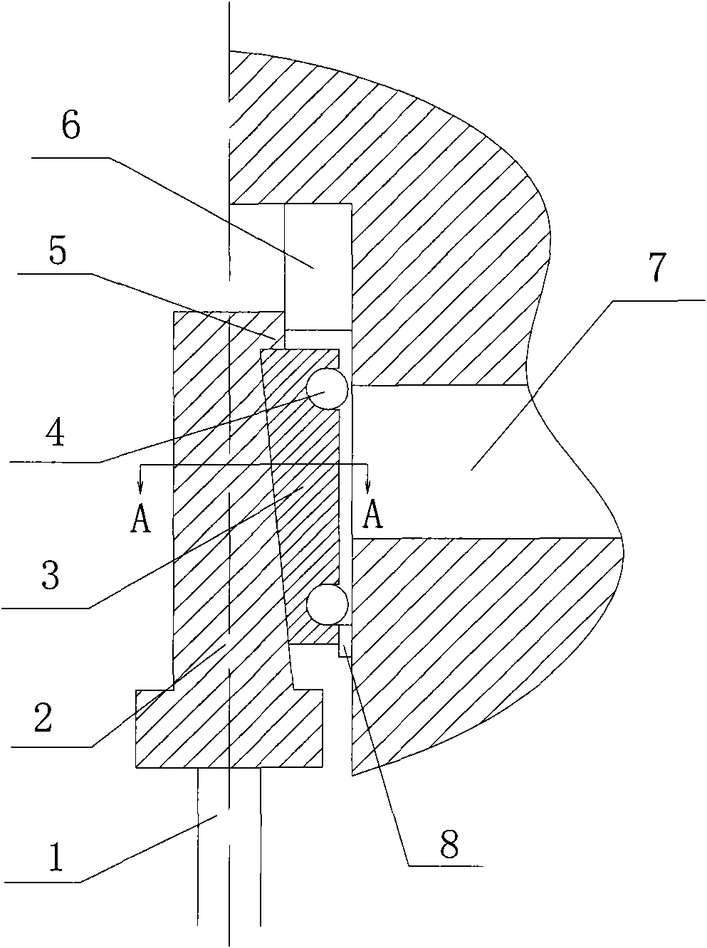
[0031] Such as image 3 As shown, the main components of the vacuum interrupting valve of the present invention include a drive rod 1, a drive mechanism 2 with a wedge-shaped slope, a stopper 5 arranged at the front end of the drive rod 1 along the slope, a sealing plate 3, and a first stopper. Advance the limit stopper 6, and the second limit stopper is the retreat limit stopper 8. The drive mechanism 2 is a wedge-shaped component with a slope, the extended surface of the slope of the drive mechanism 2 intersects the axis extension line of the drive rod, wherein the end with a larger axial distance from the slope to the drive rod 1 is its high end, and the end from the slope to the drive rod 1 The side with the smaller axis distance is its lower end. Such as image 3 As shown, the low end of the slope is close to the front end of the drive rod 1, and its low end is close to the tail end of the drive rod 1. The sealing plate 3 is slidably arranged on the slope, such as Fi...

Embodiment 2

[0036] Such as Figure 7 Shown is the cross-sectional view of this embodiment, which is different from the first embodiment in that the vacuum isolation valve of this embodiment adopts two-way sealing, and the driving mechanism 2 at the front end of the driving rod 1 is a wedge-shaped structure with two opposite slopes Correspondingly, the vacuum isolation valve of this embodiment further includes a second sealing plate 12 on which a sealing ring 4 is also arranged. The second sealing plate 12 is arranged opposite to the sealing plate 3 . The extended surfaces of the two slopes all intersect with the extension line of the drive rod 1, and the low end is close to the front end of the drive rod 1, and the high end is close to the tail end. Different from the previous embodiments, in this embodiment, the slope of the driving mechanism 2 and the two sealing plates are slidably connected through the bearing 9 , and a tension spring 11 is provided between the sealing plate 3 and th...

Embodiment 3

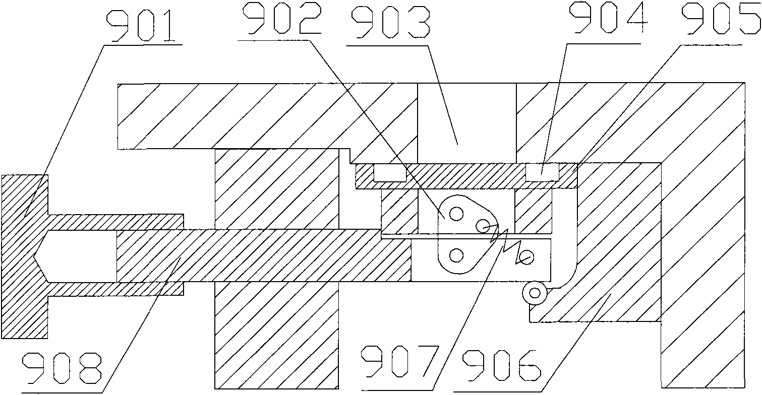
[0041] Such as Figure 8 Shown is a partial cross-sectional view of this embodiment. The difference from the previous two embodiments is that this embodiment uses a cylinder to drive the drive rod 1 to move. The vacuum isolation valve components of this embodiment also include components such as a cylinder 23 and a piston 24. . Wherein the piston 24 is installed in the cylinder 23, and the cylinder 23 is divided into a cylinder chamber 25 and a cylinder chamber 28, and the cylinder chamber 25 and the cylinder chamber 28 are connected with the pneumatic interface 26 and the pneumatic interface 29 respectively; On the piston 24, in order to ensure the airtightness between the two cylinders, a sealing ring 31 is also installed on the piston 24.

[0042] The difference between this embodiment and the second embodiment is that it also includes a positioning block 14 for guiding the sealing plate 3 and the second sealing plate 12 to complete the vacuum channel isolation and opening...


PUM


Abstract

The invention discloses a vacuum isolating valve, which comprises a driving rod, a sealing plate, a driving mechanism, and a moving direction limit mechanism, wherein the front end of the driving rod is arranged in an inner cavity of a valve body in a sliding way; the sealing plate is provided with a sealing face with a sealing medium, arranged in the inner cavity of the valve body, and can be combined or separated from the inner wall on the periphery of a port formed at an inner end of a vacuum channel in the inner cavity of the valve body to enclose or open the vacuum channel; the driving mechanism is arranged between the driving rod and the sealing plate, and is used for driving the sealing plate to be close to or far from the port; and the moving direction limit mechanism is arranged between the valve body and the sealing plate, and is used for guiding a moving part of the sealing plate close to the inner wall on the periphery of the port to move along the direction vertical to the inner wall on the periphery of the port so as to limit the relative sliding between the sealing face and the inner wall on the periphery of the port. The vacuum isolating valve adopts the moving direction limit mechanism to effectively avoid friction displacement between sealing elements in the isolating or opening, reduce abrasion, and stop scratches; and the driving rod has high rigidity, is not bent, and is durable to effectively reduce maintenance cost and ensure the performance and safety of an electric mirror.

Description

technical field [0001] The invention relates to a vacuum isolating valve, in particular to a vacuum isolating valve used for vacuum isolating the lens barrel of an electron microscope. Background technique [0002] Since its birth 30 years ago, electron microscopy has been widely used. It is not only used in the field of biomedicine to analyze the ultrastructure of human pathological specimens, but also to assist in the diagnosis of viral diseases, tumors and other diseases that seriously endanger human health; it is also widely used It is used in the industrial field, such as material defect analysis, metallurgical process analysis, thermal processing analysis, metallography, failure analysis, etc. Electron microscopy has been used as an advanced method for decades, and has made significant contributions to medical science research, clinical disease diagnosis and high-tech industrial applications. [0003] In the electron microscope, effective measures must be taken to kee...

Claims


Application Information

Patent Timeline
Patent Type & Authority Applications(China)
IPC IPC(8): H01J37/02F16K3/18F16K3/316F16K31/124H01J37/26
Inventor 刘亚琪孙占峰
Owner KYKY TECH
Why Eureka
Try Eureka