
Method for hot-rolling a slab and hot-rolling mill

A technology of hot rolling mill and rolling stand, applied in the field of hot rolling slab, which can solve problems such as damage to the characteristics of the final product

Inactive Publication Date: 2012-09-05
SMS GRP GMBH
View PDF6 Cites 9 Cited by
  • Summary
  • Abstract
  • Description
  • Claims
  • Application Information

AI Technical Summary

Problems solved by technology

In addition, due to the cold edges can impair the properties of the final product

Method used


Image

  • Method for hot-rolling a slab and hot-rolling mill
  • Method for hot-rolling a slab and hot-rolling mill
  • Method for hot-rolling a slab and hot-rolling mill

Examples


Embodiment Construction

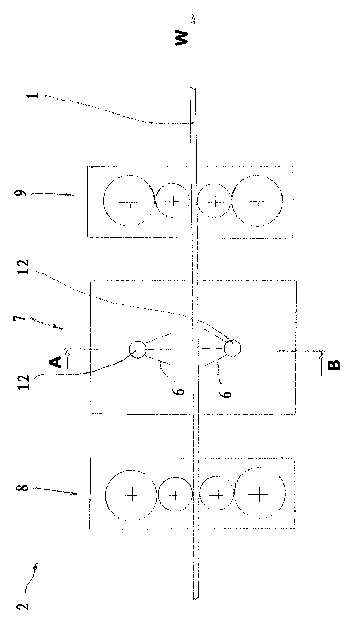
[0024] exist figure 1 A hot rolling mill 2 is depicted in , in which a slab 1 can be rolled. For this purpose, there are several hot rolling stands 8 , 9 , of which only two are shown. During rolling, the slab is conveyed in the rolling direction W and rolled in a known manner. During rolling, the slab is subjected to a thermomechanical treatment.

[0025] Accordingly, the slab 1 is subjected to a thickness reduction in the first hot rolling stand 8 . The slab 1 is cooled after the stand 8 , for which the slab 1 is guided through a cooling station 7 , which is formed here as an intermediate cooling stand.

[0026] After the cooling station 7 , the slab 1 is now re-rolled in the hot rolling stand 9 , in particular at a lower temperature than in the hot rolling stand 8 .

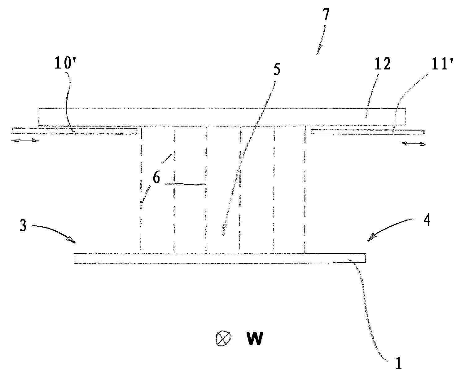
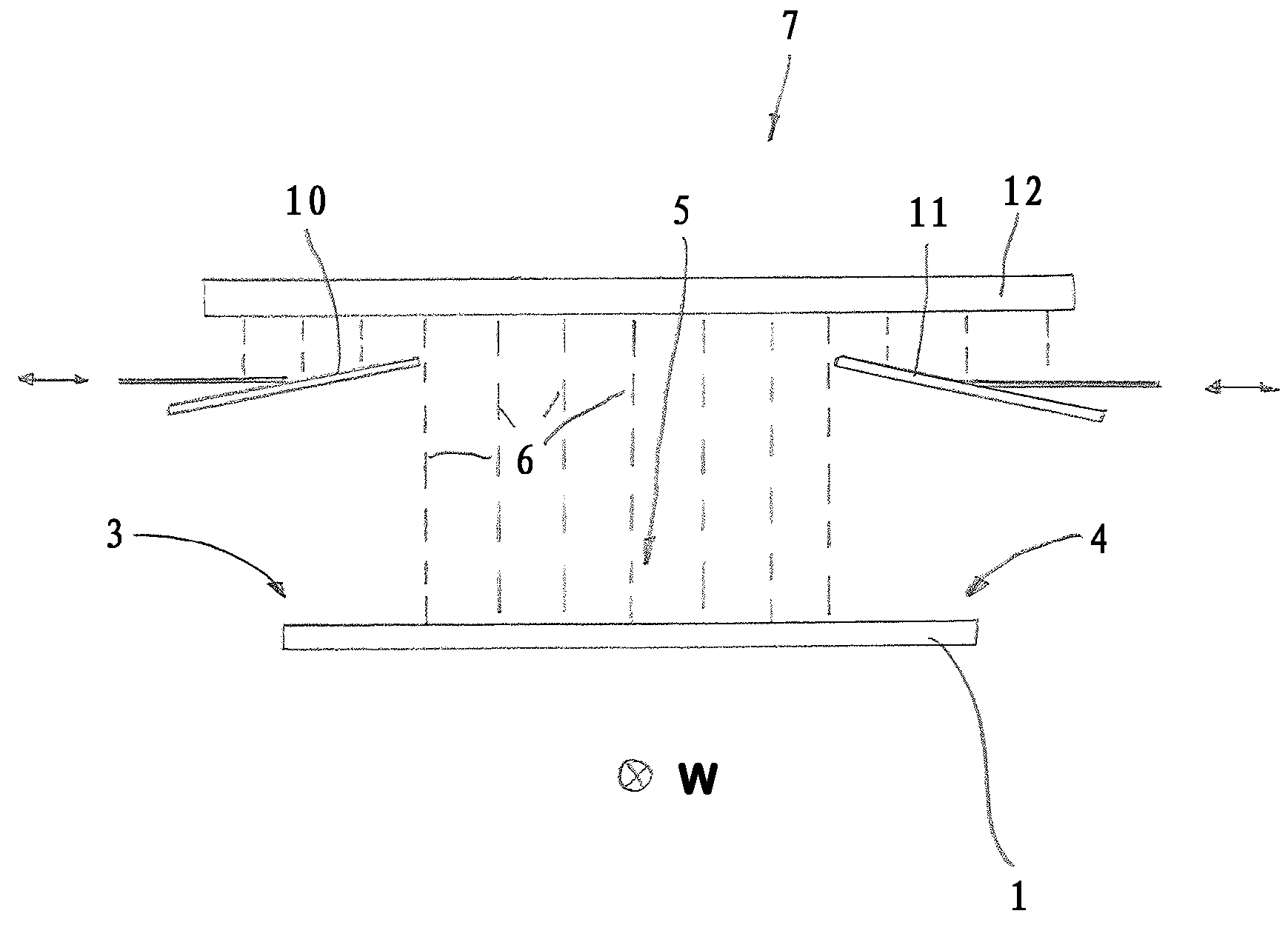
[0027] Cooling of the slab 1 takes place in the cooling station 7 by spraying a cooling medium 6 , here in the form of water. For this purpose there is the known chilled beam 12 .

[0028] from figure ...


PUM


Abstract

The invention relates to a method for hot-rolling a slab (1), especially a steel slab, the slab (1) being subjected to at least two shaping steps at different temperatures in a hot-rolling mill (2), the slab (1) being cooled between two such shaping steps. In order to prevent ferrite from forming too soon during the hot-rolling, the slab (1) is cooled such that the lateral end sections (3, 4) of the slab (1) are cooled with a lower cooling power than a center section (5) of the slab (1). The invention further relates to a hot-rolling mill (2) for hot-rolling a slab.

Description

technical field [0001] The invention relates to a method for hot rolling (Warmwalzen) slabs (Bramme), especially steel slabs, wherein the slab is subjected to at least two deformations at different temperatures in a hot rolling mill (Warmwalzwerk), Therein, the slab is cooled between two deformations of this type. Furthermore, the invention relates to a hot rolling mill for hot rolling slabs. Background technique [0002] Hot rolling of slabs is well known in the prior art. In this case, multistage hot rolling is used as a preferred method, wherein on the other hand a special method is thermomechanical (thermomechanical) rolling (TM method). [0003] A typical application of the method is the production of hot-rolled steel strips and sheets from microalloyed steels. [0004] The aim here is high homogeneity of the material produced from the hot-rolled slab, ie the material properties should be spatially constant in the material. In order to achieve this goal, the highest...

Claims


Application Information

Patent Timeline
Patent Type & Authority Applications(China)
IPC IPC(8): B21B45/02
CPCB21B45/0203B21B45/0209B21B2001/028B21B2201/06B21B2261/21B21B1/26B21B45/02
Inventor K.贝尔歇姆I.舒斯特D.施密特
Owner SMS GRP GMBH
Learn More