Tread stripes of a vehicle pneumatic tire

A technology for pneumatic tires and vehicles, applied to tire treads/tread patterns, vehicle components, tire parts, etc., can solve problems such as limited bending stiffness and limited tire durability, and achieve fine classification, high support effect, Effect of simple support area

Active Publication Date: 2015-11-25
CONTINENTAL REIFEN DEUTSCHLAND GMBH
View PDF3 Cites 0 Cited by
  • Summary
  • Abstract
  • Description
  • Claims
  • Application Information

AI Technical Summary

Problems solved by technology

[0004] In the construction with a plurality of pure transverse grooves and a plurality of transverse grooves formed between said transverse grooves in the circumferential direction, correspondingly reaching the tread base and thus possibly maintaining their function over time In the case of purely fine cuts, by virtue of the transverse grooves extending up to the tread base and the resulting limited bending stiffness of the profiled block elements, it is possible to directly in new tires in the grooves High shear forces appear on the textured bottom and the finely cut bottom This may undesirably limit the durability of the tire

Method used


Image

  • Tread stripes of a vehicle pneumatic tire
  • Tread stripes of a vehicle pneumatic tire
  • Tread stripes of a vehicle pneumatic tire

Examples


Embodiment Construction

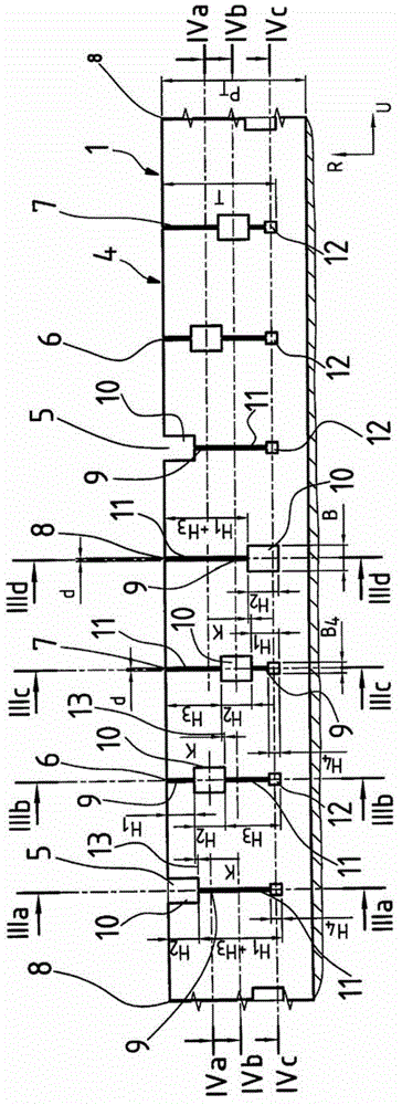
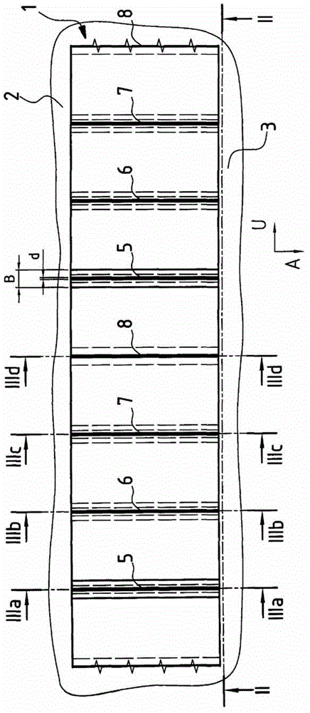
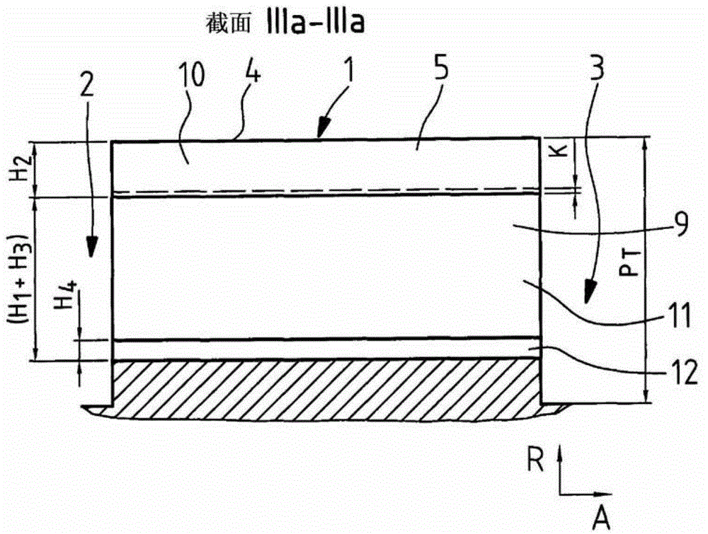
[0049] figure 1 , 2 , 3a, 3b, 3c and 3d show a circumferential rib 1 formed in the circumferential direction U of the pneumatic tire of a commercial vehicle, extending over the entire circumference of the pneumatic tire of the vehicle, and protruding in the radial direction R, the circumferential rib The vehicle pneumatic tire is delimited axially on both sides in the axial direction A by a circumferential groove 2 and 3 extending in the circumferential direction U over the entire circumference and oriented in the circumferential direction U. The circumferential rib 1 extends outward in radial direction R from the groove base of the circumferential grooves 2 and 3 and is delimited on its radially outward surface by a cover 4 which forms the ground contact surface. The circumferential grooves 2 and 3 have a maximum depth measured radially inwardly from the cover 4 to the base of said grooves, which corresponds to the tread depth P T .

[0050] Distributed in the circumferen...


PUM


Abstract

The invention relates to a tread profile of a pneumatic vehicle tire, comprising profile strips (1) that extend over the entire circumference of the pneumatic vehicle tire, wherein a plurality of transverse or oblique recesses (5, 6, 7, 8) are designed over the circumference of the pneumatic vehicle tire in at least one profile strip (1), wherein the recess (5, 6, 7, 8) in a first radial extension region (9) is designed as fine recess having a thickness d and an extension height H1 as measured in the radial direction R, and in a second radial extension region (10) is designed as a wide recess with a thickness B, with B = (2d), and an extension height H2 as measured in the radial direction R, wherein the radial positions of the first radial extension region (9) and of the second radial extension region (10) formed in relation to each other within a recess (5, 6, 7, 8) are selected to be different from each other in the recesses (5, 6, 7,8) distributed over the circumference of the tire.

Description

technical field [0001] The present invention relates to a tread pattern of a pneumatic tire for vehicles with a plurality of radially raised tread bands axially spaced apart from each other and axially upper bounded by a plurality of sipe or grooves, These tread bands extend over the entire circumference of the vehicle pneumatic tire and are bounded radially outwards by a vehicle pneumatic tire cover forming the ground-contacting surface, wherein at least one tread band is distributed over the circumference of the vehicle pneumatic tire A plurality of transversely or obliquely running incisions are formed, which each pass through the entire tread band in the axial direction A at least within the ground-bearing width TA of the pneumatic vehicle tire and start radially from the outer surface in the radial direction R extending inwards up to a depth T, wherein the cutouts each have at least a first radially extending region and a second radially extending region, wherein in the f...

Claims


Application Information

Patent Timeline
Patent Type & Authority Patents(China)
IPC IPC(8): B60C11/04B60C11/12
CPCB60C11/0306B60C11/04B60C11/12B60C11/1218B60C11/1281B60C2011/1209B60C2011/1227B60C11/0323
Inventor 徐乔托马斯·布欣格尔-巴恩斯托夫
Owner CONTINENTAL REIFEN DEUTSCHLAND GMBH
Why Eureka
Try Eureka