A deformable spatial manipulation arm

A manipulator and space technology, applied in the field of deformable space manipulators, can solve the problems of inability to rotate three-dimensional manoeuvres at the same time, reduce the degree of freedom of the claw flaps, and the complex structure of manipulators, so as to achieve spatial displacement changes and reduce self-freedom. degree, the effect of increasing flexibility

Active Publication Date: 2016-06-22
THE GENERAL DESIGNING INST OF HUBEI SPACE TECH ACAD
View PDF7 Cites 0 Cited by
  • Summary
  • Abstract
  • Description
  • Claims
  • Application Information

AI Technical Summary

Problems solved by technology

[0006] Aiming at the above defects or improvement needs of the prior art, the present invention provides a deformable spatial manipulation arm, the purpose of which is to realize the spatial displacement change of the mechanical claw by setting the telescopic rod, the rotating shaft, and the mechanical claw assembly accordingly, and the mechanical claw assembly The bionic joint of the claw is set in the middle to connect multiple knuckles, which realizes the grasping of objects of different sizes by the mechanical claw assembly. It is also equipped with a slide lock that can lock the claw flap, which can reduce the degree of freedom of the claw flap accordingly, and then can Reduce control requirements, thereby solving the technical problems in the prior art that the operating arm has a complex structure, cannot perform simultaneous rotation and three-dimensional maneuvering, and has poor adaptability

Method used


Image

  • A deformable spatial manipulation arm
  • A deformable spatial manipulation arm
  • A deformable spatial manipulation arm

Examples


Embodiment Construction

[0030] In order to make the object, technical solution and advantages of the present invention more clear, the present invention will be further described in detail below in conjunction with the accompanying drawings and embodiments. It should be understood that the specific embodiments described here are only used to explain the present invention, not to limit the present invention. In addition, the technical features involved in the various embodiments of the present invention described below can be combined with each other as long as they do not constitute a conflict with each other.

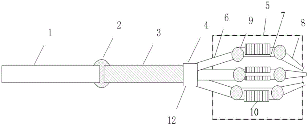
[0031] figure 1 It is a schematic diagram of the structure of the deformable spatial manipulation arm in the preferred embodiment of the present invention. It can be seen from the figure that it includes a fixed length rod 1, a telescopic rod 3, a rod bionic joint 2, a mechanical claw assembly 5, a base 4, a rotating shaft 12 and slide lock10. The length of the telescopic rod 3 can be adjus...


PUM


Abstract

The invention discloses a deformable space motion arm. The deformable space motion arm comprises a fixed-length rod, a telescopic rod, a rod bionic joint, a gripper assembly, a base, a rotating shaft and a plurality of sliding locks. The telescopic rod is connected with the fixed-length rod through the rod bionic joint. The gripper assembly is connected with the telescopic rod through the rotating shaft in the base. The gripper assembly comprises a plurality of gripper petals, and each gripper petal comprises a plurality of knuckles which are connected through gripper bionic joints, wherein the gripper bionic joints can adjust the angle between the knuckles. The sliding locks are arranged on the gripper petals in a sleeving mode, can slide on the gripper petals and are used for sliding to the gripper bionic joints to be combined together and clasped to draw and lock the gripper petals. The motion arm is simple in structure, easy to control and operate, capable of conducting rotating and three-dimensional maneuvering and high in adaptability.

Description

technical field [0001] The invention belongs to the technical field of space manipulation, and more particularly relates to a deformable space manipulation arm. Background technique [0002] Aerospace technology is one of the high-tech technologies with the most development potential in the world today, and it is an important factor to measure a country's scientific and technological strength, determine a country's international status, and ensure national security. Since the beginning of the new century, the world's aerospace powers have launched fierce competition around aerospace technology, applications and industries. [0003] Space technology and applications mainly use spacecraft as the main carrier. Developed countries such as the United States and Germany have conducted in-depth research in this field. The United States launched the "Front End Robot Technology Recent Demonstration" (FREND) project; Germany launched a comprehensive satellite on-orbit operating syst...

Claims


Application Information

Patent Timeline
Patent Type & Authority Patents(China)
IPC IPC(8): B25J18/02B25J15/10
Inventor 王星又多乐乐李之强刘萧磊
Owner THE GENERAL DESIGNING INST OF HUBEI SPACE TECH ACAD
Why Eureka
Try Eureka