Cast iron sluice gate

An iron gate and cast iron technology, applied in the field of gates, can solve the problems of poor sealing water, short service life, poor corrosion resistance, etc., and achieve the effects of reducing friction resistance, long service life and improving wear resistance.

Inactive Publication Date: 2012-09-12
YUNNAN WATER CONSERVANCY MACHINERY
View PDF6 Cites 2 Cited by
  • Summary
  • Abstract
  • Description
  • Claims
  • Application Information

AI Technical Summary

Problems solved by technology

[0002] The gates in the prior art all use rubber for water sealing, but there are certain deficiencies in using rubber water sealing,

Method used


Image

  • Cast iron sluice gate
  • Cast iron sluice gate
  • Cast iron sluice gate

Examples


Embodiment 1)

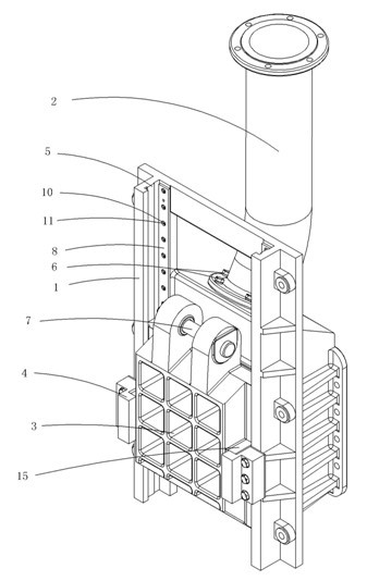
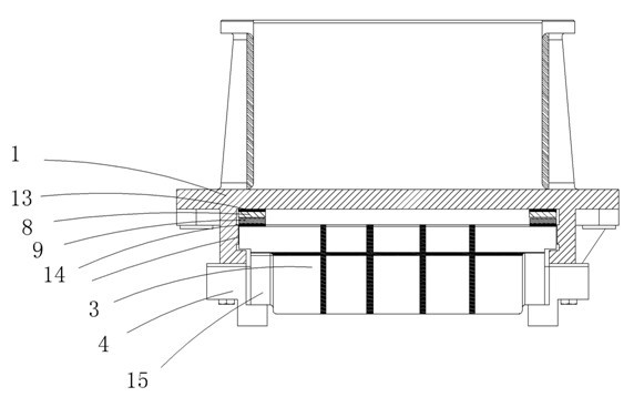
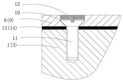
[0024] Figure 1 to Figure 3 A specific embodiment of the invention is shown in which figure 1 It is a structural schematic diagram of the present invention; figure 2 for figure 1 Transverse section of the cast iron gate shown; image 3 for figure 1 An enlarged partial cross-sectional view of a screw fastening in a cast iron gate is shown.

[0025] See Figure 1 to Figure 3 , a cast iron gate, comprising a cast iron door frame 1, a ventilation pipe 2, a cast iron door leaf 3, and a positioning device 4, one side of the cast iron door frame 1 is provided with a guide groove 5, and the ventilation pipe 2 is fixed on the cast iron door frame 1 by bolts 6, and On the upper air distribution chamber on the opposite side of the guide groove 5, the cast iron door leaf 3 is set in the guide groove 5 of the cast iron door frame 1, and the top of the cast iron door leaf 3 is set in a U shape, and the top of the U shape is connected by a suspension shaft 7. Connected, the cast iron...


PUM


Abstract

The invention discloses a cast iron sluice gate which comprises a cast iron gate frame, a ventilation pipe, a cast iron gate leaf, a positioning device and water stopping copper frames, wherein a guiding groove is arranged in one side of the cast iron gate frame; the ventilation pipe is fixedly arranged on an air distribution chamber at the upper part of one side, which is opposite to the guiding groove, of the cast iron gate frame; the cast iron gate leaf is arranged in the guiding groove of the cast iron gate frame; the top of the cast iron gate leaf is of a U-shape; the U-shaped top is connected through a hanging shaft; the cast iron door leaf is arranged in the cast iron gate frame in a vertical sliding manner; and a positioning device is arranged outside the guiding groove of the cast iron gate frame. According to the cast iron sluice gate disclosed by the invention, the water stopping copper frames are arranged on the cast iron gate frame and the cast iron gate leaf, so that the defects that a traditional gate is easy to deform and is not tight in water sealing so as to leak water and the like can be effectively solved; and in addition, due to the adoption of the cast iron gate frame and the cast iron gate leaf, the corrosion and wear resistance is greatly improved and the service life of the valve is prolonged. According to the cast iron sluice gate disclosed by the invention, the cast iron gate leaf is arranged in the guiding groove of the cast iron gate frame for connecting in a vertical sliding manner, and thus the convenience and reliability in use are realized; and a slope type positioning device is also arranged on the cast iron gate frame, so that the cast iron gate frame is matched with the cast iron gate leaf to finish the pre-pressing and locking and achieve the effect of stopping water.

Description

technical field [0001] The invention belongs to the field of gates, in particular to a cast iron gate. Background technique [0002] The gates in the prior art all use rubber for water sealing, but there are certain deficiencies in using rubber water sealing, such as water sealing is not tight, easy to leak; and not resistant to wear, easy to damage; short service life; poor corrosion resistance. Contents of the invention [0003] The object of the present invention is to provide a cast iron gate with tight water sealing, wear resistance and long service life. [0004] The technical solution to achieve the purpose of the present invention is to provide a cast iron gate, including a cast iron door frame, a ventilation pipe, a cast iron door leaf, and a positioning device. One side of the cast iron door frame is provided with a guide groove, and the ventilation pipe is fixed on the cast iron door frame by bolts. On the upper air distribution chamber on the side opposite to ...

Claims


Application Information

Patent Timeline
IPC IPC(8): E02B7/26E02B7/54
Inventor 浦理海
Owner YUNNAN WATER CONSERVANCY MACHINERY
Why Eureka
Try Eureka