Supercharge Your Innovation With Domain-Expert AI Agents!

Hydraulic return oil diffuser

A diffuser and hydraulic oil technology, applied in the hydraulic field, can solve problems such as poor diffusion effect, achieve the effect of eliminating air bubbles, increasing circulation time, and good heat dissipation effect

Active Publication Date: 2014-12-03
ZOOMLION HEAVY IND CO LTD
View PDF7 Cites 0 Cited by
  • Summary
  • Abstract
  • Description
  • Claims
  • Application Information

AI Technical Summary

Problems solved by technology

[0005] The present invention aims to provide a hydraulic oil return diffuser to solve the problem of poor diffusion effect of the hydraulic oil return diffuser in the prior art when the oil return volume is large

Method used


Image

  • Hydraulic return oil diffuser
  • Hydraulic return oil diffuser
  • Hydraulic return oil diffuser

Examples


Embodiment Construction

[0025] The embodiments of the present invention will be described in detail below with reference to the accompanying drawings, but the present invention can be implemented in many different ways defined and covered by the claims.

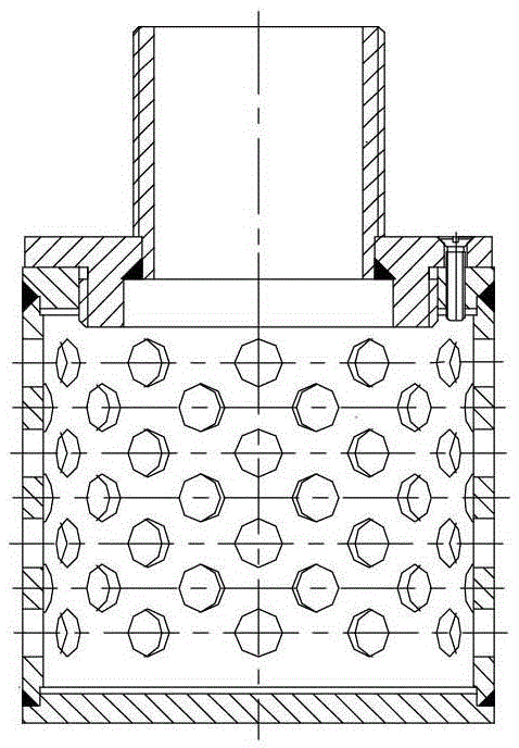
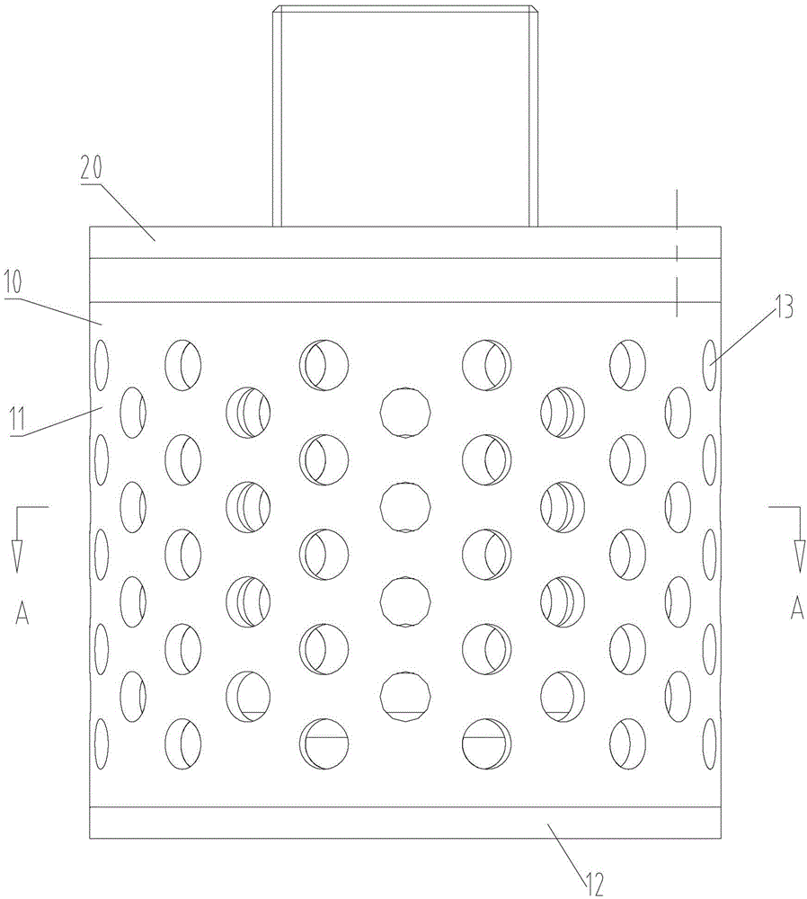
[0026] Such as Figure 3-Figure 5 As shown, the hydraulic oil return diffuser in the present invention includes: a first body 20 and a second body 10 . Wherein, the first body 20 is provided with a first hole 23 , and at least a part of the first body 20 is sheathed in the second body 10 . The second body 10 is provided with second holes 13 , and the first holes 23 and the second holes 13 are arranged alternately. Preferably, the first body 20 and / or the second body 10 is a cylinder. Since the first hole 23 and the second hole 13 are arranged alternately, the hydraulic oil flowing out from the first hole 23 will not directly flow into the hydraulic oil tank through the second hole 13, thereby prolonging the circulation time of oil return and incre...


PUM


Abstract

A hydraulic oil return diffuser includes a first main body (20) which is provided with a first hole (23) and a second main body (10), at least a part of the first main body is sleeved in the second main body. The second main body is provided with a second hole (13), and the first hole and the second hole are arranged in a staggered way. Hydraulic oil in an annular gap of the second body is forcibly disturbed through hydraulic oil flowing out of the bottom wall of the first body so as to automatically adapt to the rapid changes of return oil quantity. Bubbles can be effectively eliminated, the impact is reduced, the flow time of the return oil with instantaneous high flow rate is prolonged at the same time, and the hydraulic return oil diffuser facilitates reducing the impact and eliminating the bubbles and has a better cooling effect.

Description

technical field [0001] The invention relates to the field of hydraulic pressure, more specifically, to a hydraulic oil return diffuser. Background technique [0002] In some specific hydraulic systems (such as the distribution hydraulic system of concrete pumping equipment), the oil return of the hydraulic system is the oil discharge of the working mechanism (such as the swing cylinder), which has a large instantaneous flow rate and has a very large impact on the hydraulic oil tank. In order to reduce the impact and eliminate the oil bubbles, it is usually necessary to install such as figure 1 Hydraulic return diffuser shown. [0003] Such as figure 1 As shown, the hydraulic oil return diffuser in the prior art has a single-layer cylindrical structure, and the hydraulic oil return diffuser includes side walls on which holes are arranged. Such as figure 2 As shown, after the hydraulic oil returned to the hydraulic oil tank 100 passes through the holes of the hydraulic oi...

Claims


Application Information

Patent Timeline
Patent Type & Authority Patents(China)
IPC IPC(8): F15B21/04
CPCF15B1/26F15B21/04
Inventor 陈保钢刘建民
Owner ZOOMLION HEAVY IND CO LTD
Features
  • R&D
  • Intellectual Property
  • Life Sciences
  • Materials
  • Tech Scout
  • Unparalleled Data Quality
  • Higher Quality Content
  • 60% Fewer Hallucinations
Learn More