A 3D scene imaging method, device and display terminal

A scene imaging and scene image technology, applied in the field of 3D display, can solve the problems of low imaging accuracy and insufficient 3D effect, and achieve the effect of improving 3D imaging effect and accurate 3D imaging result

Inactive Publication Date: 2016-03-02
TCL CORPORATION
View PDF5 Cites 0 Cited by
  • Summary
  • Abstract
  • Description
  • Claims
  • Application Information

AI Technical Summary

Problems solved by technology

[0003] The purpose of the embodiments of the present invention is to provide a 3D scene imaging method, device and display terminal, aiming to solve the problems of low imaging accuracy and insufficient 3D effect after processing due to the existing 3D scene imaging processing technology

Method used


Image

  • A 3D scene imaging method, device and display terminal
  • A 3D scene imaging method, device and display terminal
  • A 3D scene imaging method, device and display terminal

Examples


Embodiment 1

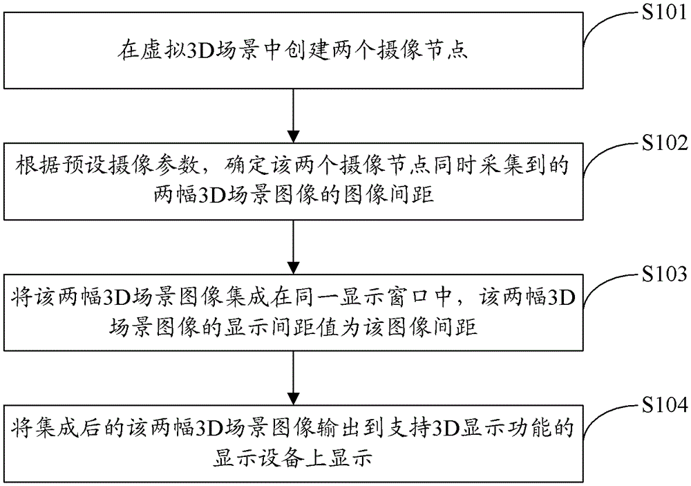
[0030] figure 1 The implementation flow of the 3D scene imaging method provided by the first embodiment of the present invention is shown, and the details are as follows:

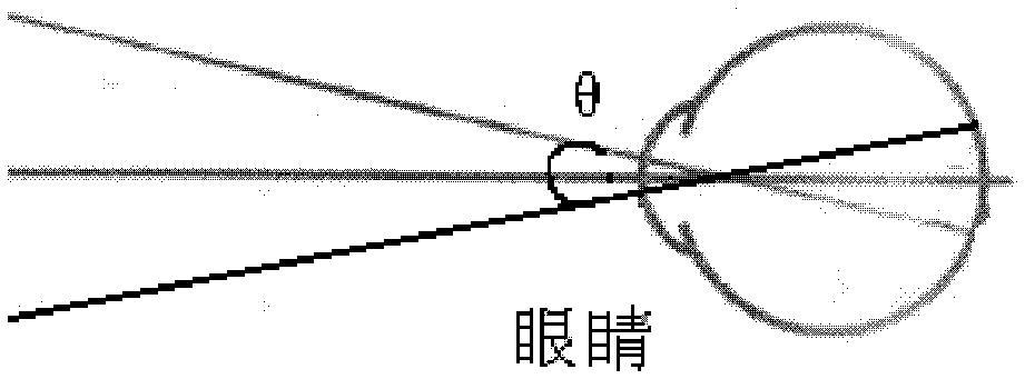
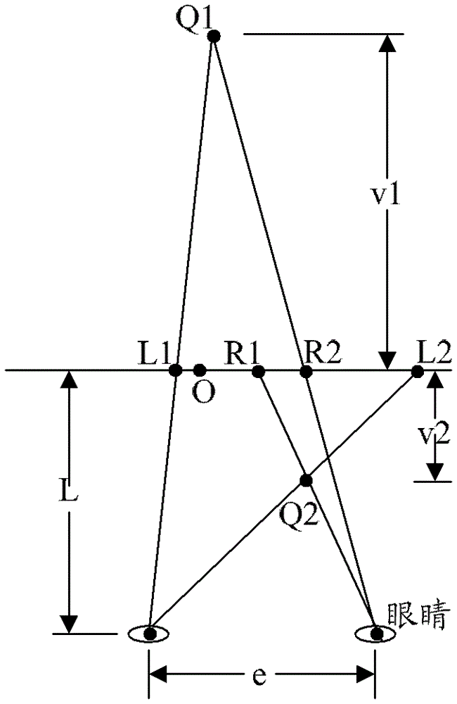
[0031] In real life, the surrounding environment that people observe through their eyes is 3D, because the two eyes of people are in different spatial positions, and two different scene images can be obtained from two different perspectives at the same time. The brain can judge the spatial information such as the distance between the object and the eyes based on the difference between the two images, forming a 3D picture and presenting it in the mind. In order to make the things in the three-dimensional scene have a 3D display effect, it is necessary to simulate the imaging method of the human eye and provide the human eye with two different image information on the left and right. Theory and experiments show that the positional relationship between the two target cameras and the 3D model, the distance bet...

Embodiment 2

[0063] Figure 10 The implementation flow of the 3D scene imaging method provided by the second embodiment of the present invention is shown, and the details are as follows:

[0064] In step S1001, two camera nodes are created in the virtual 3D scene.

[0065] In step S1002, the image distance between the two 3D scene images simultaneously collected by the two camera nodes is determined according to preset camera parameters.

[0066] In step S1003, the two 3D scene images are integrated into the same display window, and the display distance between the two 3D scene images is the image distance.

[0067] In step S1004, the two integrated 3D scene images are output to a display device supporting a 3D display function for display.

[0068] In the embodiment of the present invention, the step S1001, step S1002, step S1003, and step S1004 correspond one-to-one to the step S101, step S102, step S103, and step S104 in the first embodiment above, and will not be repeated here.

[006...

Embodiment 3

[0079] Figure 11 The structure of the 3D scene imaging device provided by the third embodiment of the present invention is shown, and for the convenience of description, only the parts related to the embodiment of the present invention are shown.

[0080] The 3D scene imaging device can be used in display terminals, or other display terminals with 3D display functions, such as televisions, etc., can be a software unit running in these display terminals, or can be integrated into these display terminals as an independent pendant In or running in the application systems of these display terminals, the 3D scene imaging device includes a camera node creation unit 111, a distance determination unit 112, a distance setting unit 113, an output unit 114, a depth value acquisition 115, a judgment unit 116 and judgment result processing Unit 117, where:

[0081] The camera node creating unit 111 is configured to create two camera nodes in the virtual 3D scene.

[0082] In the embodim...


PUM


Abstract

The present invention is applicable to the field of 3D display technology, and provides a 3D scene imaging method, device and display terminal. The method includes the following steps: creating two camera nodes in a virtual 3D scene; The image spacing of the two 3D scene images collected by the two camera nodes at the same time; the two 3D scene images are integrated in the same display window, and the display spacing value of the two 3D scene images is the image spacing; the integrated The two 3D scene images are output to a display device supporting a 3D display function for display. The invention improves the accuracy of 3D imaging and also enhances the 3D effect after imaging.

Description

technical field [0001] The invention belongs to the technical field of 3D display, and in particular relates to a 3D scene imaging method, device and display terminal. Background technique [0002] The development of 3D imaging technology has basically been affirmed by the public, mainly because it can bring the audience a greater sense of reality and on-site experience than traditional TV, and can completely bring people's eyes, ears and even thoughts into a virtual world. Going into the world of the world not only enables the audience to obtain the greatest spiritual and ideological relaxation, but also reflects a different way of life. Three-dimensional display is a technology that can reproduce image information in a true three-dimensional space with width, height and depth, and has become the first weapon used by major domestic TV manufacturers to attract users. In order to allow users to have a brand-new visual and application experience in the market competition, the...

Claims


Application Information

Patent Timeline
Patent Type & Authority Patents(China)
IPC IPC(8): G03B5/08H04N13/02H04N13/04
Inventor 卢伟超舒卫平刘超
Owner TCL CORPORATION
Why Eureka
Try Eureka