
Power allocation combining multi-antenna terminal cooperation type multiple input multiple output (MIMO) relay selection method

A multi-antenna, cooperative technology, applied in diversity/multi-antenna systems, power management, wireless communication, etc., can solve the problems of matching users to the best relay, high computational complexity, and difficult application of the system, so as to reduce energy Consumption, improved system performance, and low computational complexity

Inactive Publication Date: 2012-09-12
HARBIN INST OF TECH
View PDF1 Cites 9 Cited by
  • Summary
  • Abstract
  • Description
  • Claims
  • Application Information

AI Technical Summary

Problems solved by technology

[0004] 1. Existing research is basically aimed at the single-antenna terminal cooperative system, but there are few studies on relay selection and power allocation in the multi-antenna terminal cooperative system;
[0005] 2. At present, most of the relay selection methods are based on equal power allocation. Since the impact of power allocation on system performance is not considered, it is impossible to match the best relay for users, which limits the performance of the system;
[0006] 3. The calculation amount of the existing relay selection method is generally high, so it is difficult to apply it in the actual system

Method used


Image

  • Power allocation combining multi-antenna terminal cooperation type multiple input multiple output (MIMO) relay selection method
  • Power allocation combining multi-antenna terminal cooperation type multiple input multiple output (MIMO) relay selection method
  • Power allocation combining multi-antenna terminal cooperation type multiple input multiple output (MIMO) relay selection method

Examples


specific Embodiment approach 1

[0017] Embodiment 1. A multi-antenna terminal cooperative MIMO relay selection method combined with power allocation, which is implemented by the following steps:

[0018] Step 1: Select the value of the signal-to-noise ratio ξ between the base station and the base station at unit transmit power from all user sets that have not found a relay node i is the smallest user i, i is a random integer between 1 and the total number of users in the user set that has not found a relay node, and calculates the user i in the direct transmission mode to ensure that the bit error rate is not greater than the preset value p e The required minimum transmit power P nci ;

[0019] Step 2. Judging whether there is any user set in the candidate relay node that simultaneously satisfies ξ ij > ξ i and ξ j > ξ i M users, M is a positive integer, j is a positive integer, if the judgment result is no, execute step 21; if the judgment result is yes, execute step 22; where: ξ ij is the value of th...


PUM


Abstract

The invention discloses a power allocation combining multi-antenna terminal cooperation type multiple input multiple output (MIMO) relay selection method, and relates to a multi-antenna terminal cooperation type MIMO relay selection method. The optimal relay selection of a multi-antenna terminal cooperative system is realized, so that system performance is improved. The method comprises the following steps of: selecting a user i from a set of all users not finding a relay node, and calculating the minimum transmitted power Pnci of the user i, wherein a value xii of a signal to noise ratio between the user i and a base station is minimum under unit transmitted power, and under the minimum transmitted power Pnci of the user, a bit error rate is ensured not to be greater than a preset value pe in a direct transmission mode; selecting a user j corresponding to a minimum value of required minimum total transmitted power Pcoj as a relay user j from M users in a candidate relay node user set, wherein the xiij of each of the M users is greater than the xii, and the xij of each of the M users is greater than the xii; calculating minimum total transmitted power Pcoij required by the users i and j in a cooperative mode; and when the Pcoij is lower than the Pnci, selecting the user j as a relay node of the user i to finish the relay node selection of the user i. The method is applied to multi-antenna terminal cooperation type MIMO relay node selection.

Description

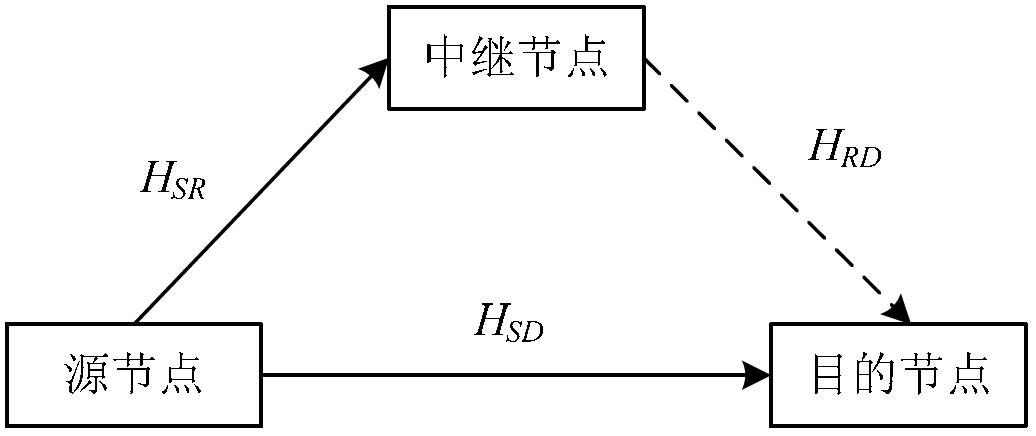
technical field [0001] The invention relates to a multi-antenna terminal cooperative MIMO relay selection method. Background technique [0002] Cooperative Diversity (Cooperative Diversity), also called Cooperative MIMO (Multiple Input Multiple Output, Multiple Input Multiple Output), is a new spatial diversity technology. Its basic idea is to use the broadcast characteristics of radio waves, and different users share each other's antennas to form a virtual MIMO system, so that diversity gain can also be obtained under the condition of a single-antenna terminal. Since the correlation between antennas of different mobile terminals is usually much smaller than the correlation between different antennas of the same mobile terminal, compared with the traditional MIMO system, the cooperative diversity system may obtain greater diversity gain. Cooperative diversity technology can be applied in many fields of wireless communication. For example, in a cellular system, cooperation ...

Claims


Application Information

Patent Timeline
IPC IPC(8): H04W52/02H04W52/42H04B7/04
CPCY02D30/70
Inventor 孟维晓韩宇辉于启月
Owner HARBIN INST OF TECH
Learn More