Dust collector for cutting machine

A dust collection device and cutting machine technology, which is applied to the attachment of sawing machines, sawing machine devices, sawing equipment, etc., can solve the problems of inconvenient use and difficulty in collecting cutting dust from saw blades, and achieve the effect of preventing poor movement

Active Publication Date: 2014-12-31
MAKITA CORP
View PDF6 Cites 0 Cited by
  • Summary
  • Abstract
  • Description
  • Claims
  • Application Information

AI Technical Summary

Problems solved by technology

However, the dust collection ruler is a device different from the cutting machine and is not a part of the cutting machine, so it is less convenient to use
In addition, when in use, since the workpiece to be cut is clamped on one side (left or right) of the saw blade by the upper side plate and the lower side plate, it is used in this state, therefore, it is difficult to collect the saw blade for another Cutting dust generated on one side

Method used


Image

  • Dust collector for cutting machine
  • Dust collector for cutting machine
  • Dust collector for cutting machine

Examples


Embodiment Construction

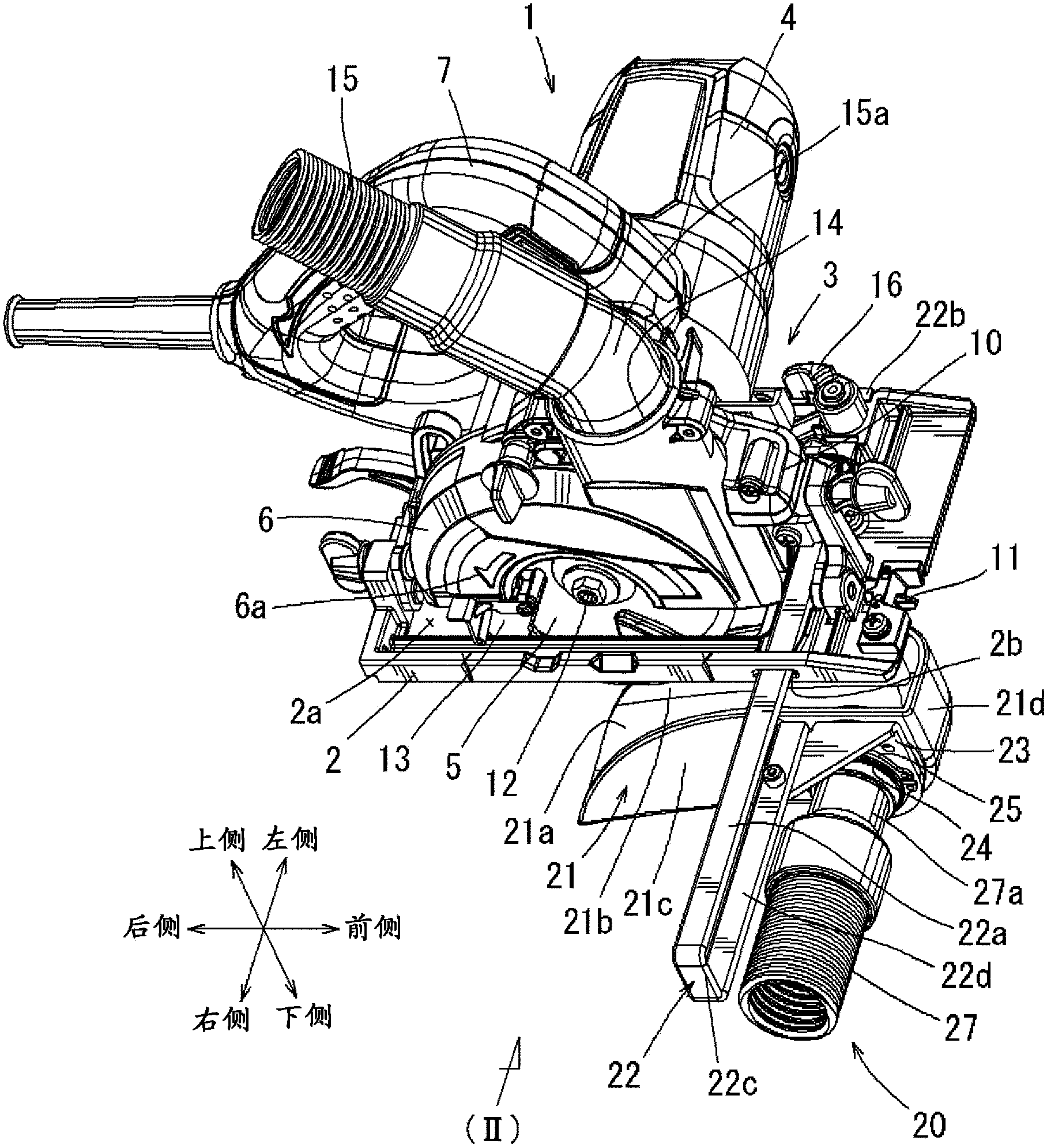
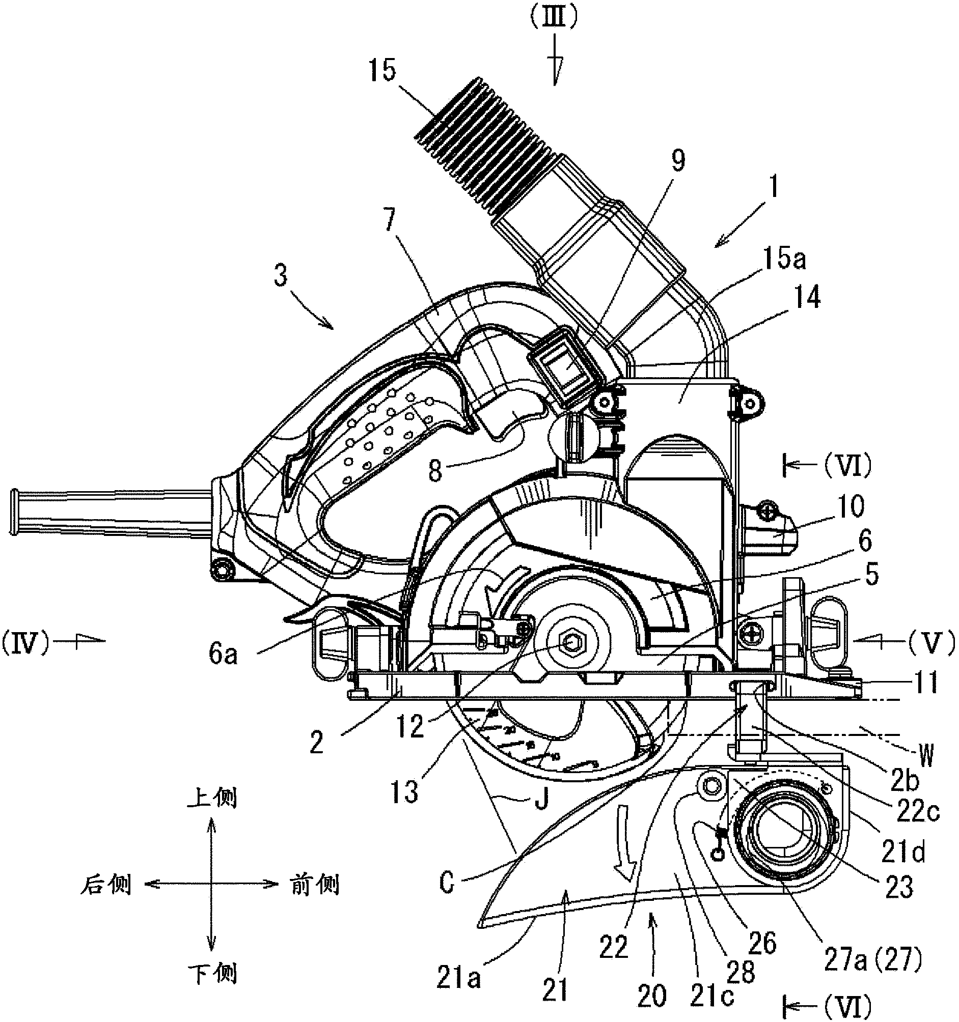
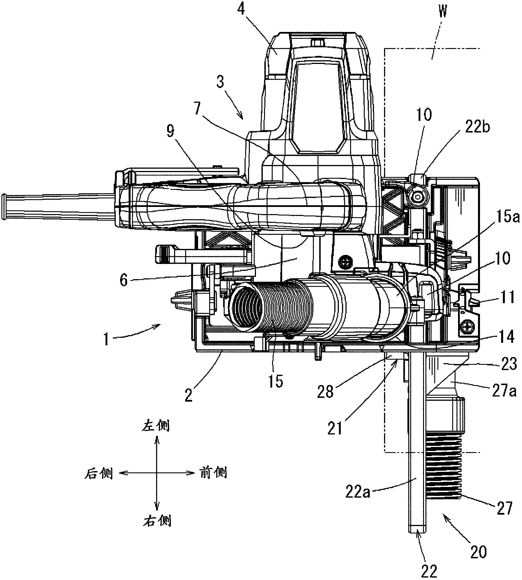
[0038] Refer below Figure 1~Figure 6 Specific embodiments of the present invention will be described. Figure 1~Figure 5 It is an overall view of the portable cutting machine 1 provided with the dust collector 20 of this embodiment. Except for the dust collecting device 20, the structure of the cutting machine 1 itself is conventionally known, and there is no special change in this embodiment, so it will only be briefly described.

[0039] In addition, in figure 1 , the user is located at the rear side of the cutting machine 1 . In the following description, front and rear, left and right, and up and down directions are all based on the user. In addition, each direction is marked in the figure.

[0040]The cutter 1 has a rectangular plate-shaped base 2 for being placed on the upper surface of a workpiece W to be cut, and a cutter main body 3 supported on the upper surface of the base 2 . The cutter body 3 has an electric motor 4 as a drive source, and a circular cutting ...


PUM


Abstract

In a portable cutting machine that is moved in a cut proceeding direction by a user in a state of being placed on a material to be cut for performing a cutting operation, dust on the lower surface side of the material to be cut was not sufficiently collected according to the related art. The present invention provides a dust collecting device with which dust collection on the lower surface side of the material to be cut can be effectively performed and the handling property is improved by configuring the dust collecting device to be removable from the cutting machine. A U-shaped supporting arm (22) is detachably attached to a base (2), and a box-shaped powder dust receiver (21) is supported directly below a cutting blade (5) via the supporting arm (22). The powder dust generated on the lower surface side of the material to be cut is received and collected by the powder dust receiver (21).

Description

technical field [0001] The invention mainly relates to a portable dust collecting device for a cutting machine. Background technique [0002] The above-mentioned portable cutting machine has a cutting machine body and a base, the cutting machine body has a saw blade driven by an electric motor to rotate, and the base is overlapped on the upper surface of the cut piece to support the cutting machine body on the cut piece superior. The user holds the cutting machine with his hand and moves it over the workpiece to cut the saw blade protruding from the lower surface side of the base into the workpiece to perform cutting work. [0003] When using this cutting machine for cutting, the rotation of the saw blade will lift up the chips and make them fly away. On the other hand, the part of the saw blade located on the upper surface side of the base is covered by the saw blade cover to prevent scattering of chips. In addition, a dust bag for collecting flying dust is connected to t...

Claims


Application Information

Patent Timeline
Patent Type & Authority Patents(China)
IPC IPC(8): B23D47/00B23D45/16B27B9/00B27G3/00
CPCB23D59/006
Inventor 高萩耕司
Owner MAKITA CORP
Why Eureka
Try Eureka