Safety cutter for jam prevention

A cutter and anti-pinch technology, applied in metal processing, sending objects, thin material processing, etc., can solve problems such as finger scratches, finger pain, unsmooth cutting, etc., and achieve the effect of safe cutting

Inactive Publication Date: 2015-05-20
吴相根
View PDF5 Cites 0 Cited by
  • Summary
  • Abstract
  • Description
  • Claims
  • Application Information

AI Technical Summary

Problems solved by technology

[0003] However, in the case of using the existing scissors to cut paper, film, fabric, etc., it is necessary to continuously use the two scissors in the state where 2 fingers including the thumb are inserted into the finger insertion ring. Parts are cut one by one, which not only takes a long time, but also has the problem of finger pain and accumulated fatigue when cutting for a long time
[0004] And, in the case of the existing scissors, since the cutting blades formed on the two scissor parts are directly exposed, especially when used by children or students, there is a possibility that fingers and the like may be scratched by the cutting blades due to carelessness. and other safety hazards, not only that, but also the problem that it is not convenient to put it in a pocket, etc. to carry
[0005] For example, another kind of knife among representative tools for cutting paper, film, fabric, etc. needs to be cut by moving the cutting blade under the state of supporting the object to be cut by the ground, so not only The ground is damaged by the cutting blade, and since the cutting blade is exposed to the outside, especially when used by children or students, there are safety problems such as the possibility of scratching fingers, etc. by the cutting blade due to carelessness, Sometimes it can also be used as a tool for hurting people, so it is classified as a dangerous carrying item
[0006] Recently, although scissors and knives are avoided, various cutting tools are being developed to cut safely and conveniently by cutting the cutting unit across the center of the cut object such as paper, film, fabric, etc. The cutting object is not smooth, especially when the cutting direction is changed to an oblique line or a curve, the cutting cannot be performed normally
[0007] In particular, in the case of a cutter in which the cutting unit is formed by a disc-shaped rotary cutting member, the disc-shaped rotary cutting member is rotatably combined with the cutter body by a fastening member such as a rivet. , there is not only the problem that when the cutting direction is changed to an oblique line or a curve, the object cut by means of the disc-shaped rotary cutting part hinders the problem of changing the direction, but it is especially used to make the disc-shaped rotary cutting part rotatable with the cutting The head of the fastening part combined with the tool body is located on the outer surface of the disc-shaped rotary cutting part, so that when the cutting direction is changed to an oblique line or a curve, the cut object cut by the disc-shaped rotary cutting part is clamped in the disc. Problems with the gap between the head of the type rotary cutting part and the fastening part

Method used


Image

  • Safety cutter for jam prevention
  • Safety cutter for jam prevention
  • Safety cutter for jam prevention

Examples


Embodiment Construction

[0055] Hereinafter, preferred embodiments of the present invention will be described in detail with reference to the accompanying drawings. This is only to enable those of ordinary skill in the art to which the present invention pertains can easily implement the present invention for the purpose of describing the present invention in detail, and does not mean that the technology of the present invention Thoughts and scope are limited to this.

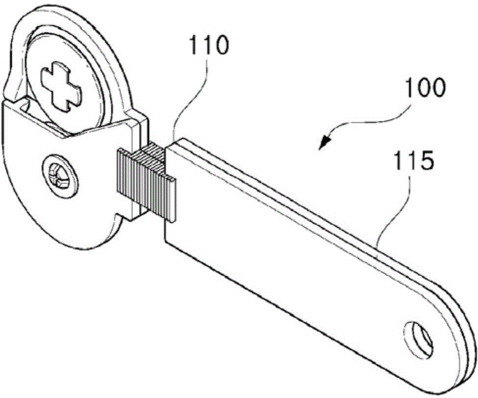
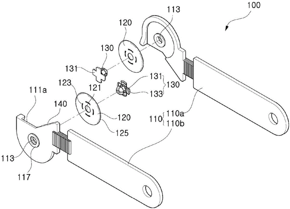
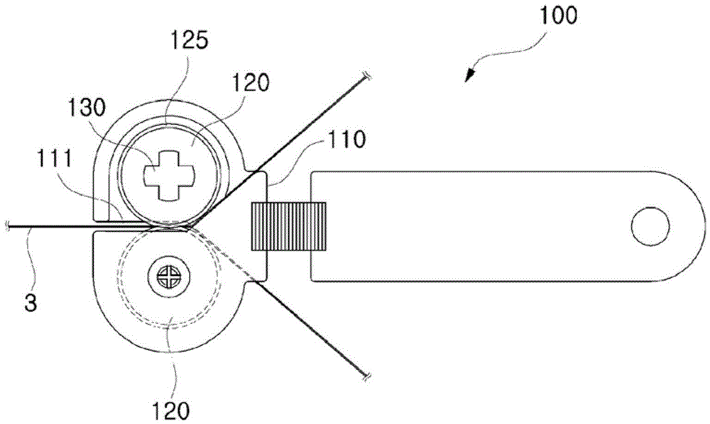
[0056] The anti-pinch type safety cutter 100 of the first embodiment of the present invention can not only make the disc-shaped rotating cutting member 120 rotate across the center of the object to be cut 3 by means of only the driving force without cutting, Thereby, the object to be cut can be cut quickly, easily and safely, and especially when the advancing direction of the disc-shaped rotary cutting member 120 is converted into an oblique line or a curve, the pinching phenomenon caused by the object to be cut can be prevented, such as...


PUM


Abstract

The present invention relates to a safety cutter for jam prevention which is capable of preventing an object being cut from being jammed when the direction of a disc-shaped rotary cutting member is switched especially in a diagonal or curved line, as well as capable of rapidly, easily and safely cutting the object being cut while the disc-shaped rotary cutting member is traversing and rotating about a center of the object being cut by means of simple pushing force without needing scissoring. The safety cutter for jam prevention according to the present invention comprises: a cutter body; disc-shaped rotary cutting members; and fastening members. In the cutter body, an open slit is formed on the front of the cutter body, coupling holes are respectively formed on the top and bottom of the open slit, and a grip part is formed on the rear of the cutter body. The disc-shaped rotary cutting members are respectively and rotatably coupled to the top and bottom of the front of the cutter body, center holes in communication with the coupling holes of the cutter body are formed in the centers of the disc-shaped rotary cutting members, insertion holes are formed to be spaced in the radial direction from the center holes, and cutting blades protruding toward the open slit and overlapping each other are respectively formed on the edges of the disc-shaped rotary cutting members. The fastening members rotatably couple the disc-shaped rotary cutting members respectively to the top and bottom of the front of the cutter body, and have center coupling protrusions in the center thereof that are coupled by sequentially penetrating the center holes of the disc-shaped rotary cutting members and the coupling holes of the cutter body, and jam prevention insertion protrusions at the outside in the radial direction that are inserted and fixed in the insertion holes of the disc-shaped rotary cutting members for preventing an object being cut from being jammed when the cutting direction is switched.

Description

technical field [0001] The present invention relates to a cutter for cutting objects to be cut such as paper, film, fabric, etc., and in more detail, to a disc-shaped rotary cutting member capable of traversing Rotate in the center of the object to be cut, so that the object to be cut can be cut quickly, easily and safely, and especially when the forward direction of the disc-shaped rotating cutting part is converted to an oblique line or a curve, it can prevent damage caused by the object to be cut Pinch-proof type safety cutter. Background technique [0002] For example, scissors, one of the representative tools for cutting paper, film, fabric, etc., are formed by intersecting two scissor parts with a cutting blade formed on one side and a finger insertion ring formed on the other side. Fasten the central part of the above-mentioned scissors parts with the help of fastening parts such as pivot pins, and use the principle of leverage to form the scissors parts with two cut...

Claims


Application Information

Patent Timeline
Patent Type & Authority Applications(China)
IPC IPC(8): B26B25/00B65H35/08
CPCB26B25/005B26B29/00
Inventor 吴相根
Owner 吴相根
Why Eureka
Try Eureka