Wire cutting device of wire electric discharge machine

a wire electric discharge machine and cutting device technology, applied in the direction of electrical-based machining apparatus, metal-working apparatus, manufacturing tools, etc., can solve the problems of wire connection failure, wire cannot be inserted smoothly, and takes time for wire connection, so as to reduce the time for cutting wire, increase tension, and reduce current

Active Publication Date: 2005-12-29
FANUC LTD
View PDF2 Cites 4 Cited by
  • Summary
  • Abstract
  • Description
  • Claims
  • Application Information

AI Technical Summary

Benefits of technology

[0017] According to the wire cutting device of a wire electric discharge machine of the present invention, when a work operation for fusing the wire develops to a specific situation (when a predetermined time elapses since the start of wire cutting, when the wire temperature reaches a predetermined temperature, or when the stretched amount of wire reaches a predetermined wire stretched amount), the current supplied to the wire is the first predetermined current value corresponding to the material and wire diameter of the wire, and increase in temperature of the wire is accelerated, whereby the time for cutting the wire can be reduced. Thereafter, the current is reduced to the second predetermined current value, tension is still continuously applied to the wire even after reducing the current, and the wire cutting is initiated during the period. Consequently, the wire end can be formed to have a pointy shape, which is suitable for automatic wire connection. Furthermore, by reducing the current applied to the wire and increasing the tension, the wire end can be prevented from being formed into a spherical shape, and the wire can be cut securely.

Problems solved by technology

However, if a current is increased too much, an end of the wire turns into a spherical shape, so the wire cannot be inserted smoothly, and it takes time for wire connection.
Moreover, wire connection may be failed.
In this manner, a value of a current supplied to a wire is determined itself, resulting in a problem where time for cutting the wire cannot be reduced.

Method used


Image

  • Wire cutting device of wire electric discharge machine
  • Wire cutting device of wire electric discharge machine
  • Wire cutting device of wire electric discharge machine

Examples


Embodiment Construction

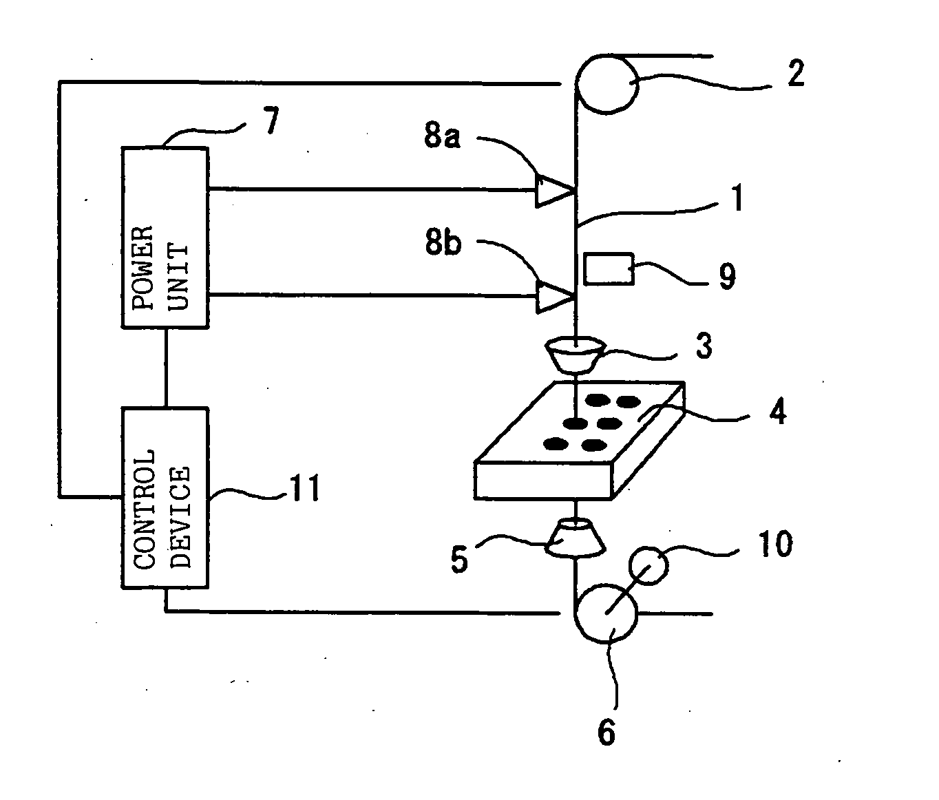
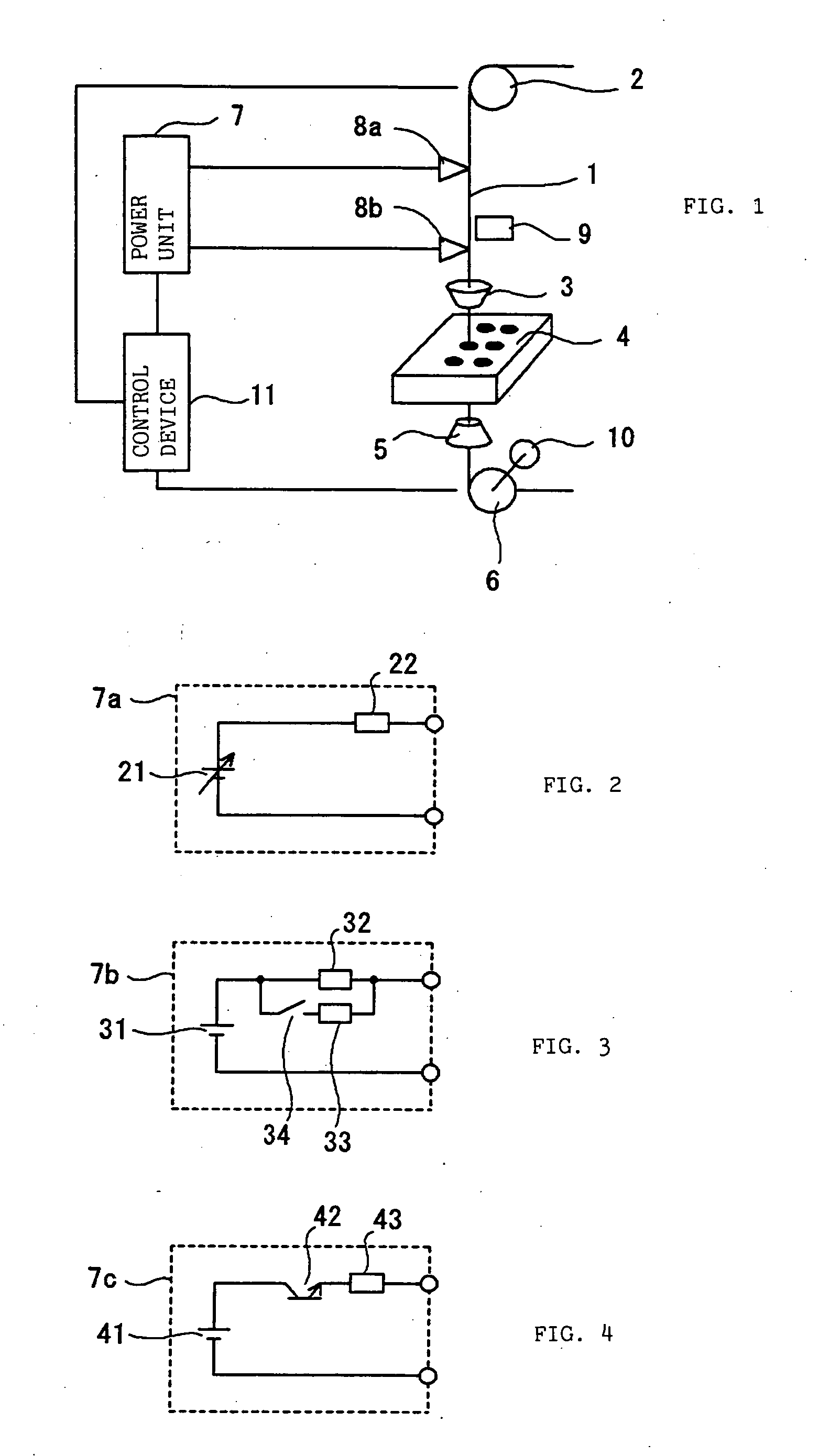
[0027]FIG. 1 is a configuration diagram showing the outline of a wire cutting device of a wire electric discharge machine which is related to an embodiment of the present invention. In FIG. 1, a wire 1 is fed by a take-up roller 6, which is rotary driven by a wire drive motor (not shown), through a roller with brake 2, an upper guide 3, a workpiece 4 of an object to be machined, and a lower guide 5. Conducting elements 8a and 8b are connected to the wire at the fusing positions, which are established between the roller with brake 2 and the upper guide 3, and a current for initiating fusion of the wire is supplied from a power unit 7 through the conducting elements 8a and 8b. Also, a wire temperature detection device 9 for detecting a wire temperature in a noncontact state with the wire is disposed so as to face the fusing positions on the wire 1. The wire drive motor (not shown) for rotary driving a brake function of the roller with brake 2 and the take-up roller 6 constitutes a ten...


PUM

PropertyMeasurementUnit
supply currentaaaaaaaaaa
diameteraaaaaaaaaa
currentaaaaaaaaaa

Abstract

When starting a wire cutting operation, a first predetermined current is supplied from a power unit to a wire, and at the same time predetermined tension is applied from a tension applying device to the wire. When a first predetermined time elapses since the start of the wire cutting operation, the current supplied from the power unit is switched to a second predetermined current which is smaller than the first predetermined current, and also the predetermined tension is continuously applied, whereby the wire is cut.

Description

BACKGROUND OF THE INVENTION [0001] 1. Field of the Invention [0002] The present invention relates to a wire cutting device of a wire electric discharge machine, which, in the wire electric discharge machine, applies a current through a wire and applies tension to fuse the wire. [0003] 2. Description of the Prior Art [0004] A wire electric discharge machine provides a machining start hole in a workpiece beforehand, inserts a wire into the machining start hole, and thereafter machines the workpiece by electric discharge. Particularly, when machining a plurality of workpieces, or when taking out a plurality of machining objects from one workpiece in continuous unattended operation, when one work is finished, a wire is cut, then a wire is automatically inserted into the next machining start hole for the next machining to be automatically connected, and the next machining is performed. Therefore, a highly reliable automatic wire cutting / connection function is absolutely necessary. This f...

Claims


Application Information

Patent Timeline
Patent Type & Authority Applications(United States)
IPC IPC(8): B23H7/04B23H7/10
CPCB23H7/102B23H7/04
Inventor NAKASHIMA, YASUOKAWAHARA, AKIYOSHI
Owner FANUC LTD
Why Eureka
Try Eureka