
Filter element and method for manufacturing filter element

一种过滤元件、密封件的技术,应用在过滤元件领域,达到保证稳定性、改进连接的效果

Active Publication Date: 2016-03-30
MANN HUMMEL GMBH
View PDF8 Cites 0 Cited by
  • Summary
  • Abstract
  • Description
  • Claims
  • Application Information

AI Technical Summary

Problems solved by technology

Of course, such a sealing foam lip can only be arranged at specific positions due to the manufacturing method

Method used


Image

  • Filter element and method for manufacturing filter element
  • Filter element and method for manufacturing filter element
  • Filter element and method for manufacturing filter element

Examples


Embodiment Construction

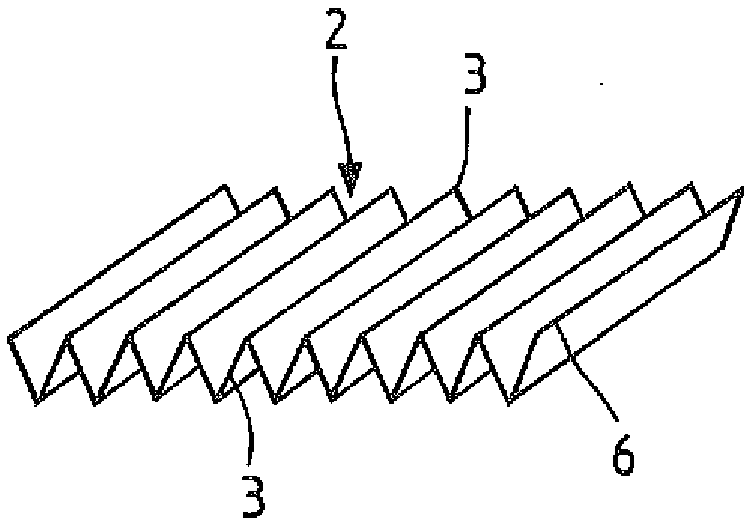
[0033] With the help of figure 1 To 3 show the first embodiment of the filter element in a simplified manufacturing state. figure 1 For this, a perspective view of the corrugated structure 2 is shown. The pleated structure 2 is formed of, for example, a filter fiber mesh material, in which a known mechanism such as a knife pleated structure or a rotary pleated structure can be used. For example, the filter fiber web material may be heat-treated to better fix the pleated profile 3. in figure 1 In the diagram, you can see the front and back fold contours 3. Reference numeral 6 shows the front end folds. Usually the side bands are now glued to the fold contour 3 in order to give stability to the entire fold structure 2. This is not necessary for the filter element proposed by the present invention.

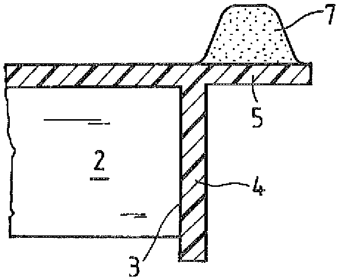
[0034] figure 2 Shows a perspective view of the corrugated structure 2 that has been provided with a plastic frame 4 of injection. The fold structure 2 is fixed to the injected pla...


PUM


Abstract

A filter element (1), eg an interior filter for a motor vehicle, comprising a pleat structure (2), a pleat contour (3) for supporting the pleat structure (2), at least partially injected into A plastic frame (4) on the corrugated structure (2) and a plastic foam seal (7) at least partially foamed on the plastic frame (4). The method for producing a corresponding filter element ( 1 ) provides that in a first injection molding process a plastic frame ( 4 ) is produced at least partially around the fold structure ( 2 ) and subsequently in a second injection molding process in the A plastic foam seal ( 7 ) is produced at least partially on the plastic frame ( 4 ).

Description

Technical field [0001] The invention relates to a filter element, in particular to an interior air filter for a motor vehicle. In addition, the present invention describes a method for manufacturing a filter element. Background technique [0002] In order to filter fluids such as fuel, other working media or interior air, for example in the automotive field, pleated or pleated filter web materials are often used. Here, it is often necessary to support the corrugation profile with auxiliary mechanisms in order to maintain the shape when the fluid flows through. In addition, it is desirable to seal the filter element on the edge of the filter element relative to the filter receptacle or the corresponding filter housing, so that unfiltered fluid will not be trapped in the pleated filter medium. Flowing by. [0003] In order to keep the zigzag filter medium stable with respect to the folds, in the past, side bands made of filter fiber mesh material were glued to the fold contours, w...

Claims


Application Information

Patent Timeline
Patent Type & Authority Patents(China)
IPC IPC(8): B60H3/06
CPCB01D46/0001B01D46/0002B01D46/10B01D46/521B01D2271/025B60H3/0608B60H2001/00635
Inventor A.拉班特
Owner MANN HUMMEL GMBH
Learn More