
Concentric sleeve type multi-layer coextrusion film blowing machine head

A multi-layer co-extrusion and sleeve-type technology, which is applied in the field of film blowing equipment, can solve the problems of large difference in length of radial runners, high precision requirements of sealing interface, and large sealing interface area, so as to reduce heat consumption, Easy sealing and low sealing precision requirements

Active Publication Date: 2014-08-20
GUANGDONG JINMING MACHINERY
View PDF3 Cites 0 Cited by
  • Summary
  • Abstract
  • Description
  • Claims
  • Application Information

AI Technical Summary

Problems solved by technology

In this way, the diameter of the die neck must be more than 1000 mm, which is obviously too large to bear
[0010]Because the eccentric distance of the position where the eccentric sprue passes through the fan-shaped area is large, that is, the distance between the eccentric sprue and the central axis of the machine head is large, which means that the die neck The diameter must be very large, which in turn causes the following problems: 1. The volume of the die neck is large, which consumes a lot of alloy steel and increases the production cost; 2. The volume of the die neck is large, resulting in long warm-up time and high energy consumption; 3. The large diameter of the neck means that the sealing interface area is large and the sealing is more difficult; 4. The large diameter of the die neck means that the total length of the runner is large and the required extrusion pressure is large, which will aggravate the difficulty of sealing and affect the sealing interface. The precision requirements are quite high
[0011]In addition, since a vertical central main channel must be arranged between the near-central ends of the adjacent two-layer material radial distribution channels, the radial distribution of the adjacent two-layer materials The distance between the near-center ends of the channel is large, while the distance between the far-center ends is small, resulting in a large difference in the length of the radial branch channels of each layer of material, which is not conducive to the pressure coordination of each layer of material extrusion.

Method used


Image

  • Concentric sleeve type multi-layer coextrusion film blowing machine head
  • Concentric sleeve type multi-layer coextrusion film blowing machine head
  • Concentric sleeve type multi-layer coextrusion film blowing machine head

Examples


Embodiment 1

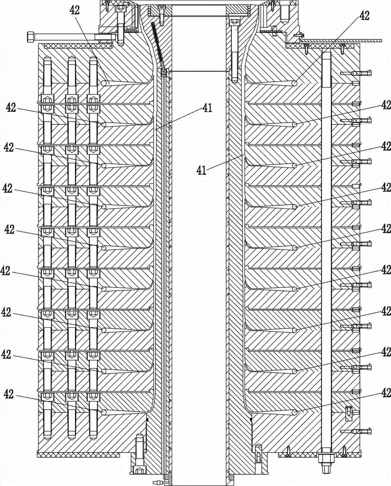
[0037] Figure 6 As shown, the concentric sleeve type multi-layer co-extrusion blown film head is provided with three-layer material flow channels.

[0038] Figure 6 , Figure 7 , Figure 12 , Figure 13 As shown, the flow path of the outermost material includes a feed inlet 31, an eccentric main flow path 32, a central main flow path 33, a radial branch flow path, and thirty-two spiral flow paths 35, and the circumferential direction between each spiral flow path 35 The spacing is the same, and the stagger between every two adjacent spiral flow channels 35 is 11.25°. Wherein the feed port 31 is connected to the eccentric main channel 32, and the eccentric main channel 32 is connected to the center main channel 33, and the radial runner of the outermost layer material comprises the peripheral section 344 of the runner and the central section 341 of the runner, and the outermost material There are thirty-two peripheral sections 344 of the runners, and the peripheral secti...

Embodiment 2

[0044] In embodiment two, the number of runners is five layers, such as Figure 15 shown.

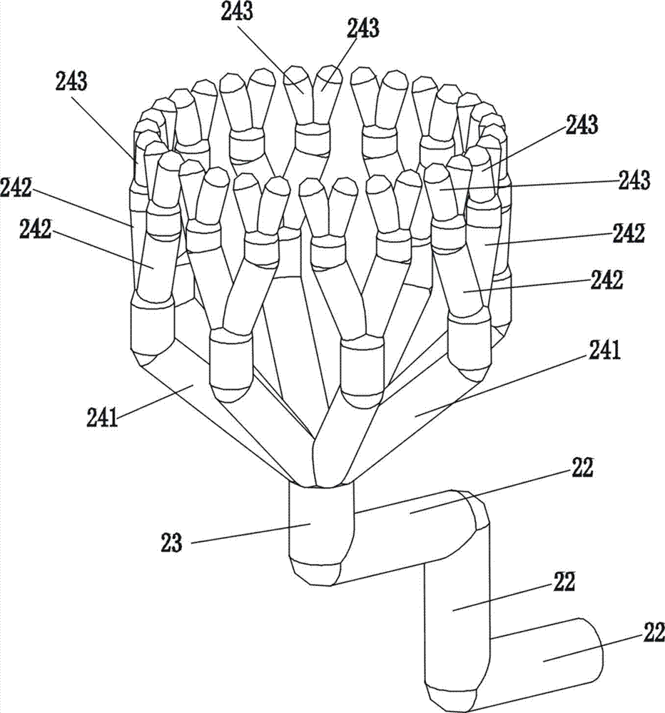
[0045]Wherein the central main channel 53 of the outermost layer material connects the eight branch channel central sections 541 of the outermost material, and the eight branch channel central sections 541 branch upwards to form sixteen branch channels, and the sixteen branch channels branch upwards to form three branches. There are twelve thin flow channels, each of which is connected to a peripheral section 544 of a branch channel, and each peripheral section 544 of a branch channel is correspondingly connected to a spiral flow channel 55 .

[0046] The central main channel 43 of the fourth layer of material is connected to the central section 441 of the eight sub-channels of the fourth layer of material, and the central section 441 of the eight sub-channels bifurcates upwards to form sixteen branch channels, and the sixteen sub-channels bifurcate upwards to form thirty There are two...

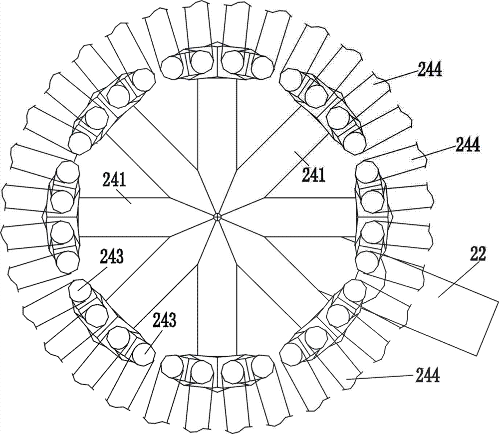

PUM


Abstract

A concentric sleeve-type multi-layer co-extrusion film blowing machine head, including several layers of material flow channels, except for the radial flow channel of the innermost material, the radial flow channel of the other layers of materials includes the peripheral section of the flow channel and the central section of the flow channel , there are N peripheral sections of the distribution channels for each layer of materials, and N / 4 in the central section of the distribution channels for each layer of materials; except for the radial distribution channels of the innermost layer of materials, the central main channel of each layer of materials connects the central sections of each distribution channel , the end of the central section of each branch channel bifurcates into two upwardly extending branch channels, and the end of each branch channel bifurcates into two upwardly extending thin flow channels, and the end of each small flow channel is connected to a The peripheral section of the runners, the end of each peripheral section of the runners is connected to a corresponding spiral flow channel; the eccentric main channel of each layer of material passes through the fan-shaped area between the central sections of the runners of the outer layer of materials. The die neck of the invention has small diameter, small die neck volume, less alloy steel consumption, and short preheating time of the machine head.

Description

technical field [0001] The invention belongs to the technical field of film blowing equipment, and in particular relates to a concentric sleeve type multi-layer co-extrusion film blowing machine head. Background technique [0002] When the multi-layer co-extrusion blown film machine is working, after each layer of material is distributed, it is finally extruded from a circular die, and then merged to form a multi-layer co-extrusion. Because the channel structure of each layer of material is relatively complicated, the multi-layer co-extrusion film blowing head must be made of very expensive special alloy steel materials. Existing multi-layer co-extrusion film blowing heads mainly contain two types, the first type is superimposed multi-layer co-extrusion film blowing heads, and the second type is concentric sleeve multi-layer co-extrusion blowing film heads. The structures of these two types of dies are very different, and the ways in which the materials of each layer are br...

Claims


Application Information

Patent Timeline
Patent Type & Authority Patents(China)
IPC IPC(8): B29C55/28B29C47/26B29C48/10B29C48/21B29C48/335B29C48/71
CPCB29C55/28B29C47/26B29C47/707B29C47/06B29C48/18B29C48/335B29C48/3363B29C48/3366B29C48/338B29C48/71B29C48/10B29C48/21
Inventor 李浩林楚漂马佳圳
Owner GUANGDONG JINMING MACHINERY
Learn More