Unlock instant, AI-driven research and patent intelligence for your innovation.
Composite wallboard and combined wallboard
What is Al technical title?
Al technical title is built by PatSnap Al team. It summarizes the technical point description of the patent document.
A composite wallboard and panel technology, applied in the direction of walls, building components, buildings, etc., to achieve the effect of reducing decoration links, beautiful appearance, and saving construction funds
Active Publication Date: 2012-09-19
广东创璟新材料科技有限公司
View PDF8 Cites 30 Cited by
Summary
Abstract
Description
Claims
Application Information
AI Technical Summary
This helps you quickly interpret patents by identifying the three key elements:
Problems solved by technology
Method used
Benefits of technology
Problems solved by technology
In this patent, it is impossible to fix the panels together through the vertical keel and the transverse tie rod
Method used
Image
Click on the blue label to locate the original text in one second.
Reading with bidirectional positioning of images and text.
Examples
Embodiment 1
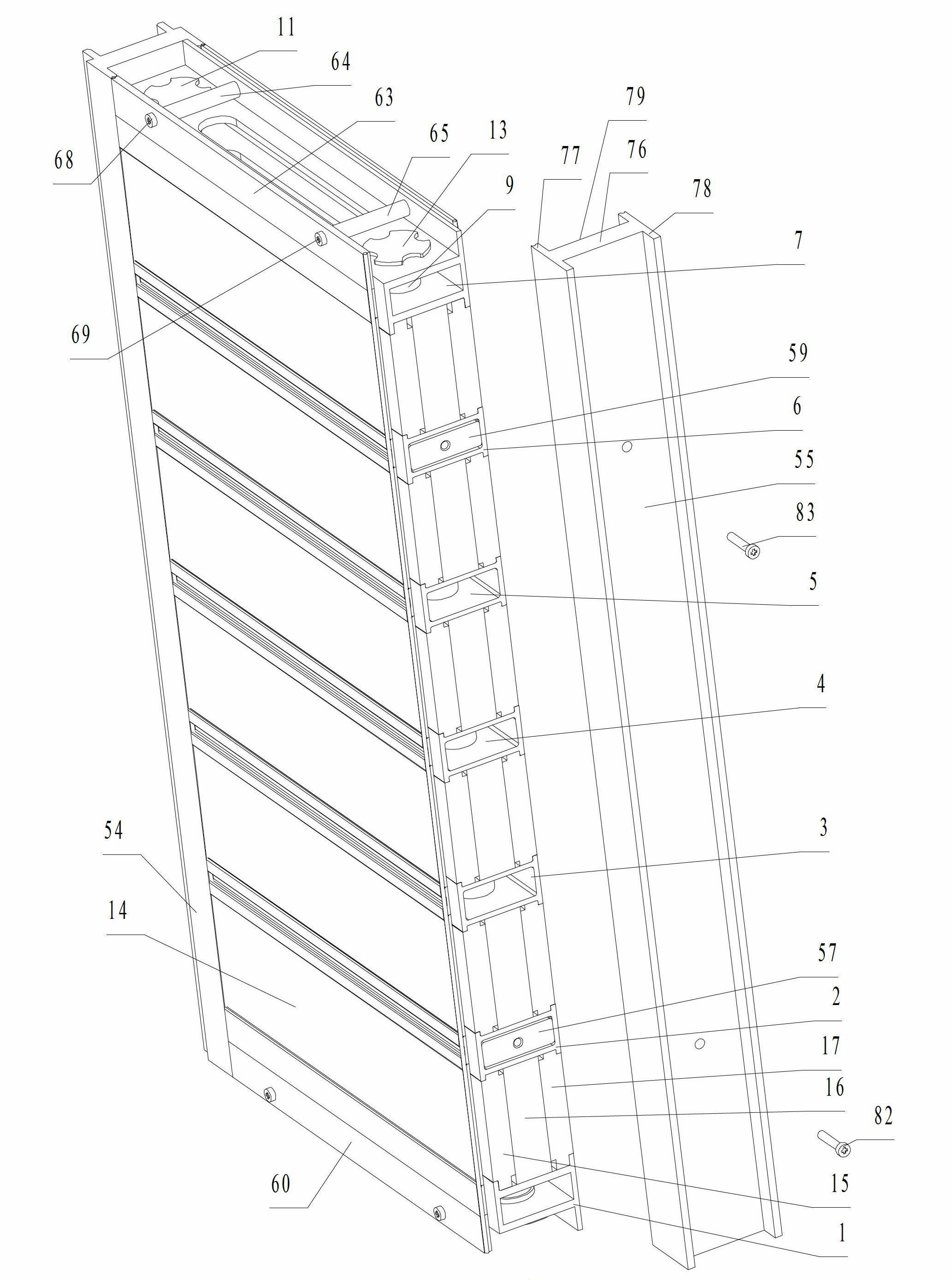
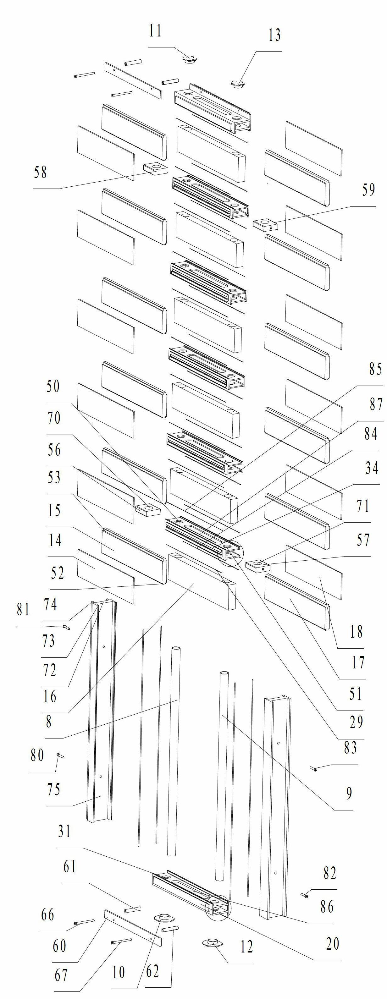
[0059] Such as figure 1 , figure 2 As shown, a composite wall panel, including horizontally installed from bottom to top, parallel lower keel 1, middle keel 2, middle keel 3, middle keel 4, middle keel 5, middle keel 6, upper keel 7, fixed Shaft 8, fixed shaft 9, locking parts 10 and 11 installed at both ends of the fixed shaft 8, locking parts 12 and 13 installed at both ends of the fixed shaft 9, installed between the lower keel 1 and the middle keel 2 Between, or between the middle keel 2 and the middle keel 3, or between the middle keel 3 and the middle keel 4, or between the middle keel 4 and the middle keel 5, or between the middle keel 5 and the middle keel 6, or between the middle keel 6 Panel 14, dividing plate 15, dividing plate 16, dividing plate 17, panel 18 installed sequentially from front to back between upper keel 7.
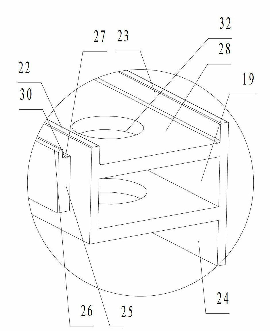
[0060] Such as figure 2 , image 3 As shown, the lower keel 1 is a profile, including a square tube-shaped keel body 19, a first positioni...
Embodiment 2
[0067] Such as Figure 5 As shown, the difference from Example 1 is that no partition is installed in the cavity formed by the adjacent keel and the panel, but the cement filling layer is poured through the elongated through hole on each keel, that is, the cement pouring hole 110 111.
Embodiment 3
[0069] Such as Image 6 As shown, the difference from Embodiment 1 is that a composite wallboard includes horizontally installed from bottom to top, parallel lower keel 120, middle keel 121, middle keel 122, middle keel 123, middle keel 124, middle keel Keel 125, middle keel 126, upper keel 127, two fixed shafts 128, locking pieces 130 installed at both ends of the fixed shaft 128, installed between the lower keel 120 and the middle keel 121, or between the middle keel 121 and the middle keel 122 , or between the middle keel 122 and the middle keel 123, or between the middle keel 123 and the middle keel 124, or between the middle keel 124 and the middle keel 125, or between the middle keel 125 and the middle keel 126, or between the middle keel 126 and the middle keel Panels 134 , partitions 135 , partitions 136 , partitions 137 , and panels (not shown) are sequentially installed between the upper keels 127 from front to back.
[0070] The lower keel 120, the middle keel 121,...
PUM
Abstract
The invention discloses a composite wallboard and a combined wallboard. The composite wallboard comprises keels, panels and fixing shafts, wherein locking pieces are arranged at two ends of each fixing shaft; first positioning grooves which are matched with the panels are formed in the keels; more than two first positioning grooves of which the openings are in the same direction are formed in each keel; the panels are arranged in the first positioning grooves opposite to two adjacent keels; a double-layer panel is arranged between every two adjacent keels; the fixing shafts penetrate through corresponding first through holes in each keel and then are fixed together with the locking pieces; the locking pieces block the keels along the axial directions of the fixing shafts; the keels block the panels along the axial directions of the fixing shafts; and the keels, the panels and the fixing shafts are assembled together. The composite wallboard has the advantages of simple structure, is easy and convenient to mount, and can be used as an outer wall and an inner wall. When used as an outer wall body, the composite wallboard cannot crack and leak water, so that the outer wall is not required to be subjected to secondary heat preservation treatment and water repellent treatment and is not required to be subjected to a surface treatment process of painting or bonding wall tiles; and the panels are not required to be fixed together with the keels through fastening pieces or glue and the like.
Description
technical field [0001] The invention relates to a wallboard, in particular to a composite wallboard composed of a keel and a panel and a composite wallboard installed together by multiple sets of composite wallboards. Background technique [0002] In the utility model patent No. 94247873.8, a joint structure of a steel frame, a wall panel, a ceiling, and a roof is disclosed. Punch multiple lugs at equal intervals on the side of the profile lug bar of the steel frame. The lug strips are divided into A type and B type. One side is a vertical lug, and the other side is a horizontal lug; the panels are also divided into A-type panels and B-type panels. The side edge of the character ", the other side is the end of the word "one", and a hook cavity and hook must be set in the middle, with the side edge of the word "ji" (or "B") and the end of the word "one" on the other panel The side and the ear are socketed and meshed together, and the cycle goes round and round, and multiple...
Claims
Application Information
Patent Timeline
Application Date:The date an application was filed.
Publication Date:The date a patent or application was officially published.
First Publication Date:The earliest publication date of a patent with the same application number.
Issue Date:Publication date of the patent grant document.
PCT Entry Date:The Entry date of PCT National Phase.
Estimated Expiry Date:The statutory expiry date of a patent right according to the Patent Law, and it is the longest term of protection that the patent right can achieve without the termination of the patent right due to other reasons(Term extension factor has been taken into account ).
Invalid Date:Actual expiry date is based on effective date or publication date of legal transaction data of invalid patent.
