Device and method for stopping water when heading device enters into receiving well

A water stop device and receiving well technology, which is applied to mining equipment, earthwork drilling, tunnels, etc., can solve problems such as inability to ensure complete water stop, failure, and non-wearable airbags

Active Publication Date: 2012-09-19
SHANGHAI FOUND ENG GRP
View PDF8 Cites 6 Cited by
  • Summary
  • Abstract
  • Description
  • Claims
  • Application Information

AI Technical Summary

Problems solved by technology

But adopting the airbag waterproof method has the following disadvantages: A. the airbag is relatively large, and the production cost is high
And once a little air leaks, all of them will fail; B. The airbag is not wear-resistant, and it is easy to fail due to the magic break under the frictional movement of the shield; C. Under higher water pressure, there are common problems of the previous two methods, that is, Complete water-tightness cannot be guaranteed and is therefore likely to fail

Method used


Image

  • Device and method for stopping water when heading device enters into receiving well
  • Device and method for stopping water when heading device enters into receiving well
  • Device and method for stopping water when heading device enters into receiving well

Examples


Embodiment 1

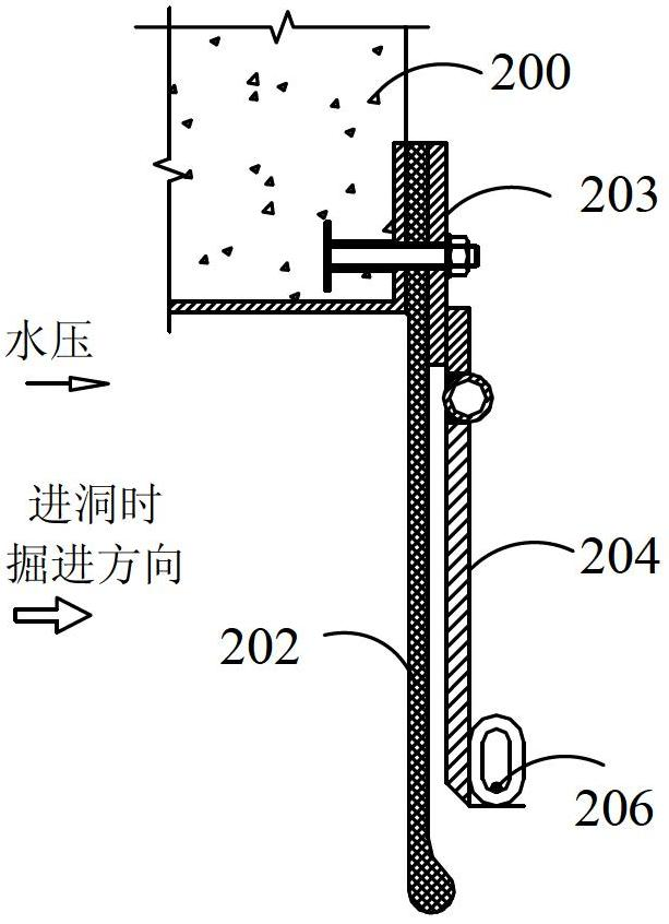
[0052] see image 3 , image 3 It is a structural schematic diagram of the water stop device when the excavation equipment enters the receiving well according to the first embodiment of the present invention. This embodiment provides a water stop device when the tunneling equipment enters the receiving well, which is used to stop the water when the tunneling equipment 300 enters the receiving well. Since the water is outside the receiving well, that is, outside the hole, the water pressure is mainly It is squeezed from the outside of the hole to the inside of the hole, where the water flows will generate water pressure at that position. The water stop device when the excavation equipment enters the receiving well: it includes an elastic cord 302 such as a rubber cord, a flap 304 and a pressing plate 303, and one end of the elastic cord 302 is fixedly installed on the periphery of the door opening of the enclosure structure 300 through the pressing plate 303, so The flap 304 ...

Embodiment 2

[0069] see Figure 10 The difference between this embodiment and Embodiment 1 is that the water-tight casing is installed around the door opening of the enclosure structure 300 through the support casing 400, and one end of the support casing 400 is fixed on the enclosure structure 300 Around the door opening, the other end of the support box 400 is installed with a door seal 500, the water-stop box is installed on the annular inner wall of the support box 400, and one end of the elastic cord 302 in the water-stop box is fixed by a pressure plate 303 on the annular inner wall of the support box 400 . The second connection holes 307 are respectively fixedly connected with the corresponding positions on the annular inner wall of the support box 400 and the corresponding movable plate, and the water stop device also includes a number of first bolt assemblies annularly distributed along the annular inner wall of the support box 400 310 , the first bolt assembly 310 fixedly instal...

Embodiment 3

[0074] see Figure 11 , the difference between this embodiment and the second embodiment is: the number of the support sleeves 400 is two or more, the number of the water-tight sleeves is the same as the number of the support sleeves 400, the support The casings 400 are connected sequentially, wherein, the end of the supporting casing 400 close to the enclosure structure 300 is fixedly connected to the periphery of the enclosure structure 300, and the end of the supporting casing 400 away from the enclosure structure 300 is far away from the enclosure. The end of the structure 300 is provided with the sealing door 500, and the water-tight casings are respectively arranged on the annular inner walls of the corresponding support casings 400, and one end of the elastic cord 302 in each water-tight casing is fixed to the corresponding pressure plate 303. The annular inner wall of the supporting sleeve 400. In this embodiment, leak-stopping materials may also be filled between mul...


PUM


Abstract

The invention discloses a device and a method for stopping water when a heading device enters into receiving well. The device comprises a water stopping sleeve box, the water stopping sleeve box is directly installed on the periphery of a door opening of a space enclosing structure or installed on the periphery of the door opening of the space enclosing structure through a support sleeve box, the water stopping sleeve box comprises an elastic cord fabric, a turning plate and a pressing plate, one end of the elastic cord fabric is fixed by the pressing plate, the turning plate comprises a plurality of movable plates which are distributed in a circular ring shape, an upturned clamping portion is arranged at an end of each of the movable plates of the turning plate, the end of each of the movable plates of the turning plate is far away from the pressing plates, one end of the elastic cord fabric is attached to the turning plate, and the other end of the elastic cord fabric is turned up and at least wrap up the clamping portions. The water stopping device further comprises first traction ropes, one ends of the first traction ropes are sequentially connected to each of the movable plates of the turning plate, and a position of the clamping portion of each of the movable plates of the turning plate can be controlled by controlling the first traction ropes. According to the device and the method for stopping water when the heading device enters into receiving well, water stopping effects are reliable and same when the heading device enters the receiving well and goes out of an original well, and the process is simple.

Description

technical field [0001] The invention relates to the technical field of building construction, in particular to a water-stopping device and method when excavation equipment enters a receiving well. Background technique [0002] There are two key procedures in the existing pipe jacking and tunnel construction: going out of the originating shaft (that is, exiting the tunnel) and entering the receiving shaft (that is, entering the tunnel). These two key processes all involve the setting of the water stop device. [0003] The water-stopping devices and water-stopping methods for existing excavation equipment (such as shield tunneling, pipe jacking, etc.) entering the receiving well mainly have the following forms: [0004] 1. Use the excavation equipment water stop device for reference. The principle of the hole water stop device is: see Figure 1a and Figure 1b , when the excavation equipment 101 goes out of the hole, push the flap 104 and the elastic cord 102 (usually rubbe...

Claims


Application Information

Patent Timeline
Patent Type & Authority Applications(China)
IPC IPC(8): E21D9/14
Inventor 陈建波
Owner SHANGHAI FOUND ENG GRP
Why Eureka
Try Eureka