Piezoelectric vibrator bilateral fluid driven series connection pump

A piezoelectric vibrator and double-sided drive technology, which is applied in the field of series pumps, can solve the problems of chip-type piezoelectric vibrator damage, reduce the energy efficiency and reliability of the piezoelectric hydraulic drive, and reduce the overall effective power output of the drive, so as to improve the output. The effect of flow

Inactive Publication Date: 2012-09-19
ZHEJIANG NORMAL UNIVERSITY
View PDF11 Cites 11 Cited by
  • Summary
  • Abstract
  • Description
  • Claims
  • Application Information

AI Technical Summary

Problems solved by technology

The reason is: the deformation of the piezoelectric vibrator is extremely small, and the actual fluid is compressible. The piezoelectric hydraulic drive must use an accumulator to provide back pressure to increase the rigidity of the system and avoid the piston of the hydraulic cylinder from crawling; but due to the piezoelectric vibrator or the pump cavity One side of the diaphragm is in contact with the fluid. At this time, the system back pressure has become the load of the piezoelectric vibrator, seriously reducing the overall effective power output of the driver. When the system back pressure is too large, it will also cause damage to the wafer-type piezoelectric vibrator, reducing the Energy Efficiency and Reliability of Piezohydraulic Actuators

Method used


Image

  • Piezoelectric vibrator bilateral fluid driven series connection pump
  • Piezoelectric vibrator bilateral fluid driven series connection pump
  • Piezoelectric vibrator bilateral fluid driven series connection pump

Examples


Embodiment Construction

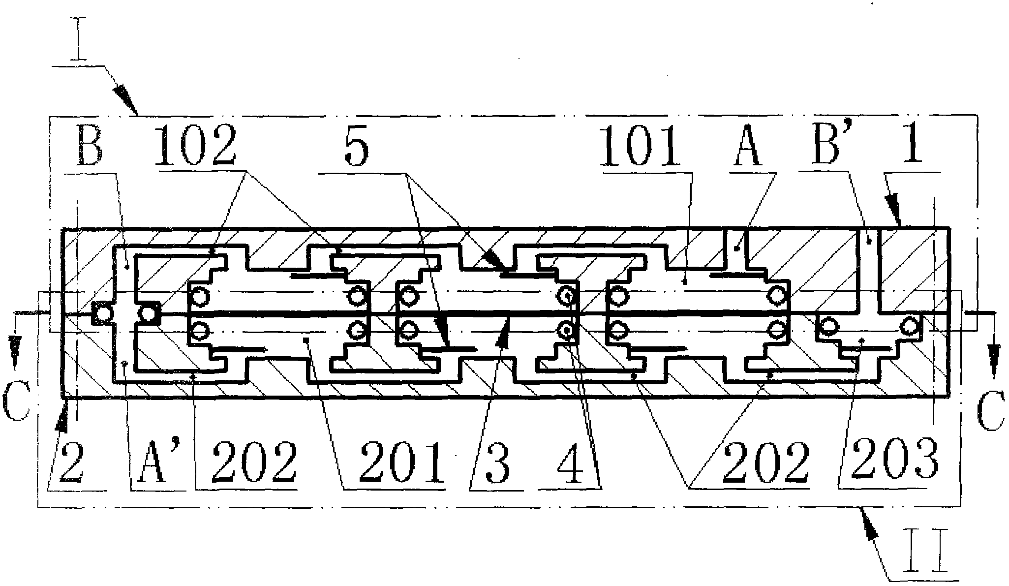
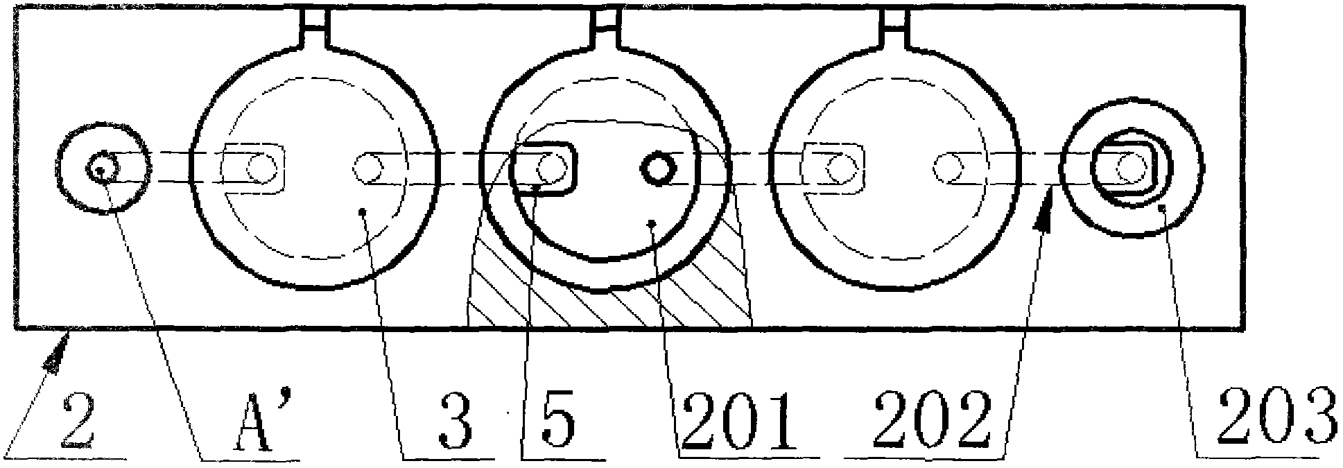
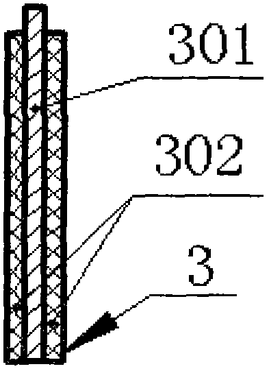
[0016] Such as figure 1 , figure 2 , as shown in Figure 3, the upper pump body 1 and the lower pump body 2 are connected by screws; 2-20 piezoelectric vibrators 3 are crimped on the pump cavity 101 on the upper pump body 1 and the lower pump body 2 through the sealing ring 4 Between the upper pump chamber 201, the piezoelectric vibrator 3 is formed by bonding a metal substrate 301 and a piezoelectric wafer 302; at the entrance of the pump chamber 101 of the upper pump body 1 and the pump chamber 201 of the lower pump body 2 The valve plate 5 is bonded to the inlet of the valve chamber 203; on the upper pump body 1, the external inlet A communicates with the adjacent pump chamber 101, and the gap between the two adjacent pump chambers 101 and the internal outlet B communicates with adjacent pump chambers 101 through inter-chamber channels 102, the external inlet A on the upper pump body 1, the series pump chamber 101, the internal outlet B, and the pump chamber 101. The valv...


PUM


Abstract

The invention relates to a piezoelectric vibrator bilateral fluid driven series connection pump and belongs to the fields of fluid transmission and control. An upper pump body and a lower pump body are connected through a screw, 2-20 piezoelectric vibrators are connected between pump cavities of the two pump bodies in a pressed mode, and valve blocks are pasted at the position of inlets of the pump cavities and an inlet of a valve cavity of the lower pump body. An external inlet of the upper pump body is communicated with adjacent pump cavities, two adjacent pump cavities are communicated through an inter-cavity runner to be connected with the are communicated through an inter-cavity runner to be connected with the piezoelectric vibrators to form a series connection pump I, and an internal outlet and the adjacent pump cavities are communicated through an inter-cavity runner to be connected with the piezoelectric vibrators to form the series connection pump I. an internal inlet of the lower pump body and the adjacent pump cavities are communicated through an inter-cavity runner to be connected with the piezoelectric vibrators to form a series connection pump II, the two the adjacent pump cavities are communicated through an inter-cavity runner to be connected with the piezoelectric vibrators to form the series connection pump II, and a valve cavity and the adjacent pump cavities are communicated through an inter-cavity runner to be connected with the piezoelectric vibrators to form the series connection pump II. An internal outlet of the series connection pump I and the internal inlet of the series connection pump II are communicated, the valve cavity of the series connection pump II is communicated with the external outlet on the upper pump body. The piezoelectric vibrator bilateral fluid driven series connection pump has the advantages that the plurality of the piezoelectric vibrators with two sides driving the fluid simultaneously form series connection piezoelectric pumps, flow quantity is big, pressure and energy efficiency are high, and the piezoelectric vibrator bilateral fluid driven series connection pump is applicable to construction of piezoelectric hydraulic driving with high system backpressure.

Description

technical field [0001] The invention belongs to a micro precision piezoelectric pump applied in the field of microfluid transmission and control, and in particular relates to a serial pump in which a piezoelectric vibrator drives fluid on both sides. Background technique [0002] As an important part of microelectromechanical systems, the research on piezoelectric pumps has been widely concerned by scholars at home and abroad. The original piezoelectric pump was only for the purpose of microfluidic output. After decades of development, some types of piezoelectric pumps have been used in chemical analysis, biopharmaceuticals, medical drug controlled release and other microfluidic delivery and control. . In addition to simple fluid transportation, in recent years, people have also based on piezoelectric pump-driven micro-hydraulic systems, referred to as piezoelectric hydraulic drivers or piezoelectric hydraulic motors: such as Chinese patents 200810051156.7, 200920093242.4, ...

Claims


Application Information

Patent Timeline
Patent Type & Authority Applications(China)
IPC IPC(8): F04B43/04
Inventor 王淑云阚君武蒋永华曾平程光明
Owner ZHEJIANG NORMAL UNIVERSITY
Why Eureka
Try Eureka