Cage barrier spliced outer rotor stator electro-magnetic synchronous motor and control method thereof

A technology of rotor stator and synchronous motor, which is used in motor generator control, electronic commutation motor control, synchronous generator and other directions, can solve the problem of poor coupling effect of two sets of stator windings, complicated manufacturing process, and large-scale stator dual-winding AC motors. Application difficulties, etc.

Active Publication Date: 2015-06-24
SHENYANG POLYTECHNIC UNIV
View PDF6 Cites 0 Cited by
  • Summary
  • Abstract
  • Description
  • Claims
  • Application Information

AI Technical Summary

Problems solved by technology

The radial laminated salient pole reluctance rotor with cogging is easy to process, but the coupling effect on the two sets of stator windings is not good; the axial laminated reluctance rotor has strong coupling ability, but the manufacturing process is complicated. Difficult to use in AC motors
In addition, in addition, the control system of a conventional AC motor with a double set of windings placed on the stator is greatly affected by uncertain parameter changes and disturbances, and has disadvantages such as poor anti-interference ability

Method used


Image

  • Cage barrier spliced outer rotor stator electro-magnetic synchronous motor and control method thereof
  • Cage barrier spliced outer rotor stator electro-magnetic synchronous motor and control method thereof
  • Cage barrier spliced outer rotor stator electro-magnetic synchronous motor and control method thereof

Examples


Embodiment Construction

[0071] The present invention is described in detail below in conjunction with accompanying drawing:

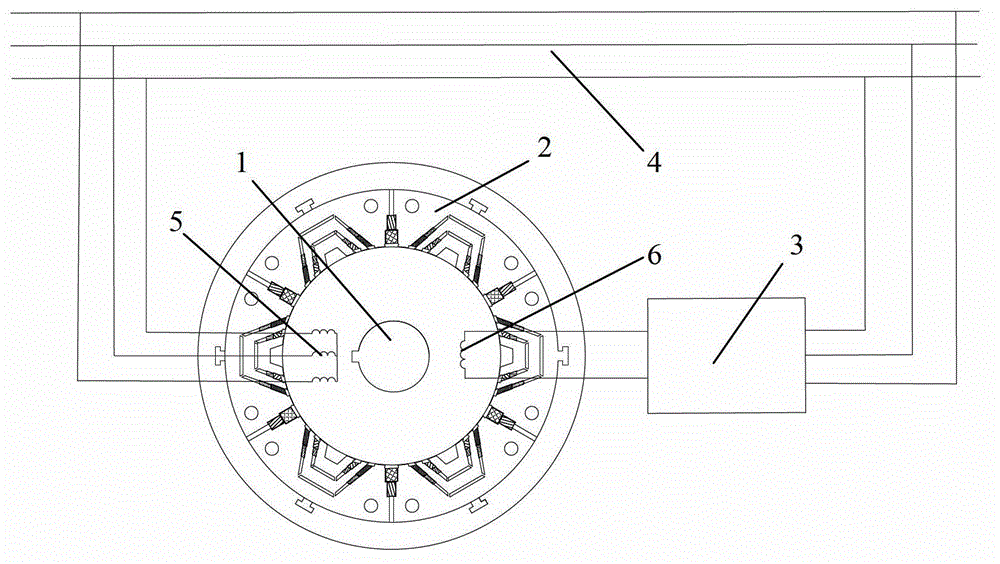
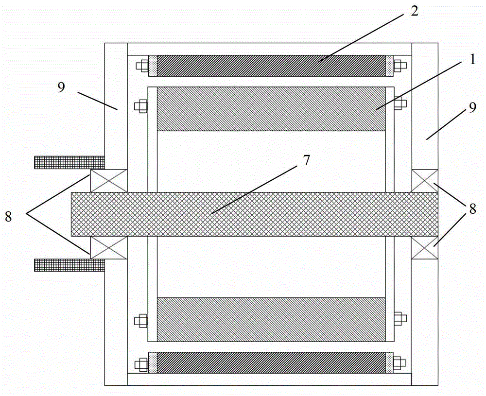
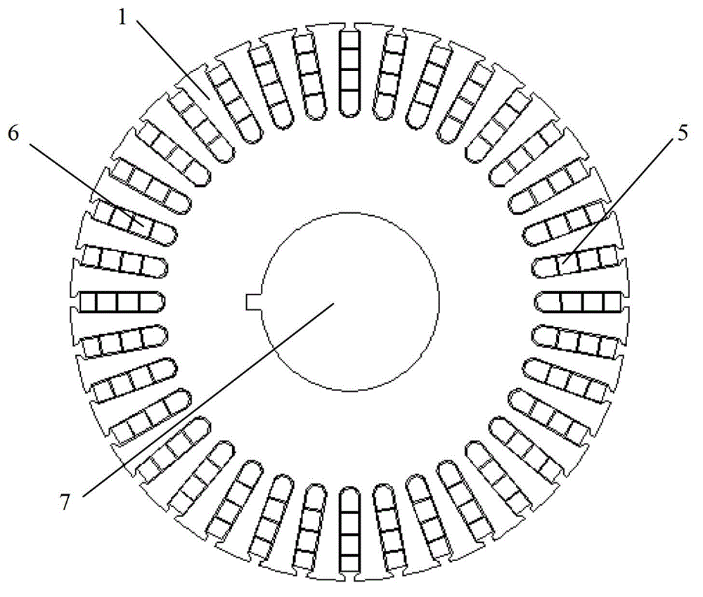
[0072] figure 1 It is a schematic structural diagram of the outer rotor stator electric excitation synchronous motor system with cage barrier assembly of the present invention. The system mainly includes a stator 1, an outer rotor 2, and a controllable DC power supply 3, wherein a three-phase symmetrical armature winding 5 with 2p poles is placed on the stator 1 and The single-phase symmetrical excitation winding 6 with 2q poles, the number of poles of the armature winding 5 and the number of poles of the excitation winding 6 can also be interchanged, but they all satisfy 2p-2q≥4, which can realize the electromagnetic coupling of two sets of stator windings with different pole numbers maximize. The armature winding 5 is connected to the grid 4 , and the field winding 6 is connected to one end of the controllable DC power supply 3 . The controllable DC power supply 3 provides...


PUM


Abstract

The invention relates to a cage barrier spliced outer rotor stator electro-magnetic synchronous motor and a control method thereof. The motor is characterized in that an outer rotor is positioned outside a stator, a three-phase armature winding and a single-phase exciting winding are arranged in slots of the outer surface of the stator, and the same cage barrier outer rotor modules are connected with a sleeve made of a non-permeability magnetic material through positioning slots and spliced in a circumferential direction to form the outer rotor with inner salient pole types; the inner surface of each cage outer rotor module is provided with radial trapezoid-shaped slots which have multiple step slot widths along a radial direction, and short circuit cage bars are arranged in the slots; after the adjacent rotor modules are spliced, common trapezoid-shaped slots are formed on connection parts of the modules, gaps of the bottoms of the slots reach the inner surface of the sleeve, the slots have multiple step slot widths along the radial direction, and common cage bars are arranged in the slots; and the invention aims to provide the cage barrier spliced outer rotor stator electro-magnetic synchronous motor which is convenient to process and manufacture, can realize the stator-side excitation, and has high power density and the excellent steady state and dynamic performance.

Description

Technical field: [0001] The invention relates to a synchronous motor, in particular to a cage-barrier assembled outer rotor stator electric excitation synchronous motor and a control method thereof. The motor can be operated as a motor or as a generator. Background technique: [0002] The stator of the cage-assembled outer rotor stator electric excitation synchronous motor includes a three-phase symmetrical armature winding with 2p poles and a single-phase symmetrical excitation winding with 2q poles (or a three-phase symmetrical armature winding with 2q poles and a single-phase symmetrical armature winding with 2p poles excitation winding), and satisfy 2p-2q≥4, the coupling between the two sets of windings is by p r =p+q is achieved by a specially designed rotor for poles, so this type of motor does not need to install brush slip rings, and can realize electromechanical energy conversion through the interaction between the magnetic field of the excitation winding and the m...

Claims


Application Information

Patent Timeline
Patent Type & Authority Patents(China)
IPC IPC(8): H02K19/14H02K19/16H02P21/00
Inventor 张凤阁贾广隆刘光伟金石王秀平
Owner SHENYANG POLYTECHNIC UNIV
Why Eureka
Try Eureka