

Hydraulic control type test method for hydraulic balance valve
A technology of hydraulic balance and test method, which is applied in fluid pressure actuation system testing, fluid pressure actuation devices, mechanical equipment, etc., can solve the problems of poor consistency and interchangeability of hydraulic balance valves, and achieve improved interchangeability, Guaranteeing the effect of conformance requirements
- Summary
- Abstract
- Description
- Claims
- Application Information
AI Technical Summary
Problems solved by technology
Method used
Image

Examples
Embodiment Construction
[0014] The technical solution of the present invention is further described below in conjunction with the accompanying drawings, but the scope of protection is not limited to the description.
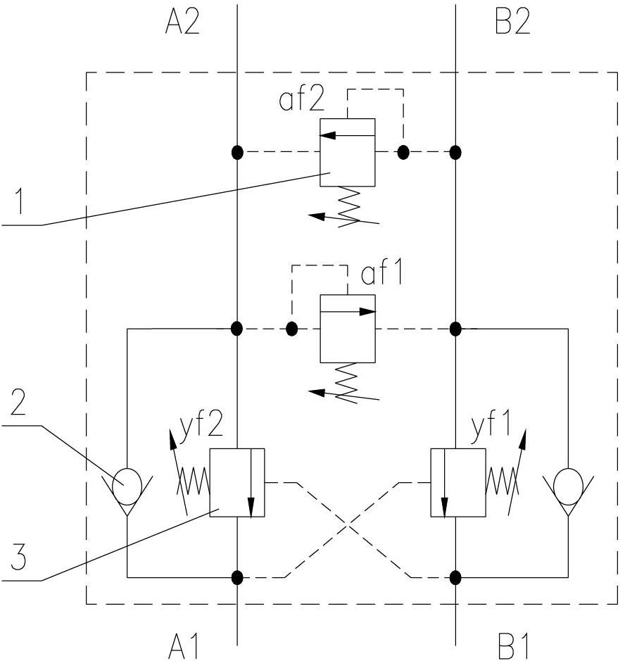
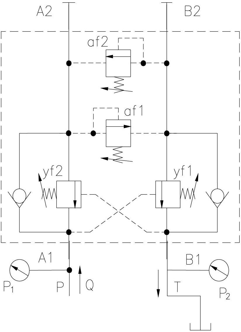
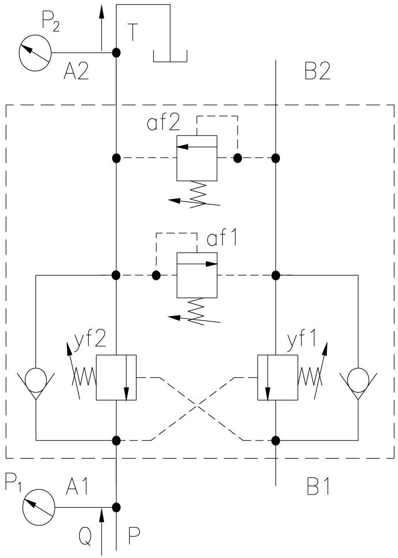
[0015] Such as figure 1 As shown, the liquid-controlled hydraulic balance valve of the present invention is mainly composed of a safety valve 1, a one-way valve 2, and a back pressure regulating valve 3. The present invention also relates to a test method for a liquid-controlled hydraulic balance valve, Firstly, the safety pressure value of the safety valve is obtained by adjusting and locking the safety valve, and then the forward flow resistance and reverse flow resistance of the single channel of the hydraulic balance valve are obtained through the single-channel flow resistance test (forward channel, reverse channel). Finally, the flow resistance of the entire balance valve is calculated by shorting the oil port.
[0016] The hydraulic control type hydraulic balance valve working p...
PUM
 Abstract
Description
Claims
Application Information